
Ni-Cd Baterry Charger 12-18V

This charger circuit is designed for the efficient and safe charging of Nickel-Cadmium (Ni-Cd) batteries, which are known for their longevity and ability to undergo numerous charge cycles. The circuit includes a current selection switch (S2) that allows the user to choose between three charging currents: 50mA, 200mA, and 400mA. This flexibility is particularly useful for charging batteries of varying capacities and conditions.
The circuit employs LED indicators to provide visual feedback. LED D9 serves as a charging indicator, illuminating when the circuit is actively charging a battery. LED D10 is crucial for safety; it indicates whether the battery is correctly connected and checks for any incorrect polarity, thereby preventing potential damage to the battery or the charger itself.
The transformer in this circuit is rated at 220V with dual 12V outputs, providing a maximum current of 0.5A, which is suitable for the charging requirements of Ni-Cd batteries. The design incorporates a variety of resistors and capacitors to manage current flow and stabilize voltage levels during operation.
The components list includes:
- Resistors: R1, R4, R5 are 10K ohms; R2, R3 are 100K ohms; R6, R8, R10 are 1K ohms; R7 is 820 ohms; R9 is 100 ohms; R11 is 15 ohms; R12 is 3.9 ohms; R13 is 1.8 ohms.
- Capacitors: C1 is a 1000µF/40V capacitor, providing necessary smoothing for the power supply; C2 is a 470pF capacitor, likely used for high-frequency noise filtering.
- Diodes: D1-D4 and D6 are 1N4001 to 1N4007 diodes, which are used for rectification; D7 and D8 are 1N4148 diodes, typically used for signal routing or protection.
- LEDs: D9 and D10 are standard LEDs for visual indicators.
- Integrated Circuit: IC is a 741 operational amplifier, which may be used for voltage regulation or current sensing.
- Transistors: TR1 is a BC548, TR2 is a BD137, and TR3 is a 2N3055, which are used for switching and amplification within the circuit.
This detailed configuration ensures that the charger operates efficiently, providing a safe and reliable means to recharge Ni-Cd batteries while maximizing their lifespan.A clever charger circuit that safely can charge any Ni-Cd battery. Offers charge current sellection, polarization detection and protection and the ability to connect many batterys in siries. Ni-Cd bateries can be recharged more than 1000 times before become useless. the charging current shoud be the 1/10 of the (Ah) of the battery. The bateries need 14 hours to be fully charged.. Swhitch S2 is the current selection as folows: 50mA, 200mA and 400mA. LED D10 is the indicator for proper batery connection and/or wrong polarity checking. LED D9 is the charging indicator. The transformer is a 220V/2x12V 0.5A. PARTS: R1,R4,R5=10K R2,R3=100K R6,R8,R10=1K R7=820 R9=100 R11=15 R12=3,9 R13=1,8 C1=1000uF/40v C2=470pf D1-D4,D6=1n4001-7 D7,D8=1n4148 D9,D10=LED IC=741 TR1=BC548 TR2=BD137 TR3=2N3055
Related Circuits
This is a simple 12V car battery charger circuit designed to address common issues found in most car battery chargers. One major problem is that if the charger remains on, the battery can overcharge, potentially damaging the charger plates...
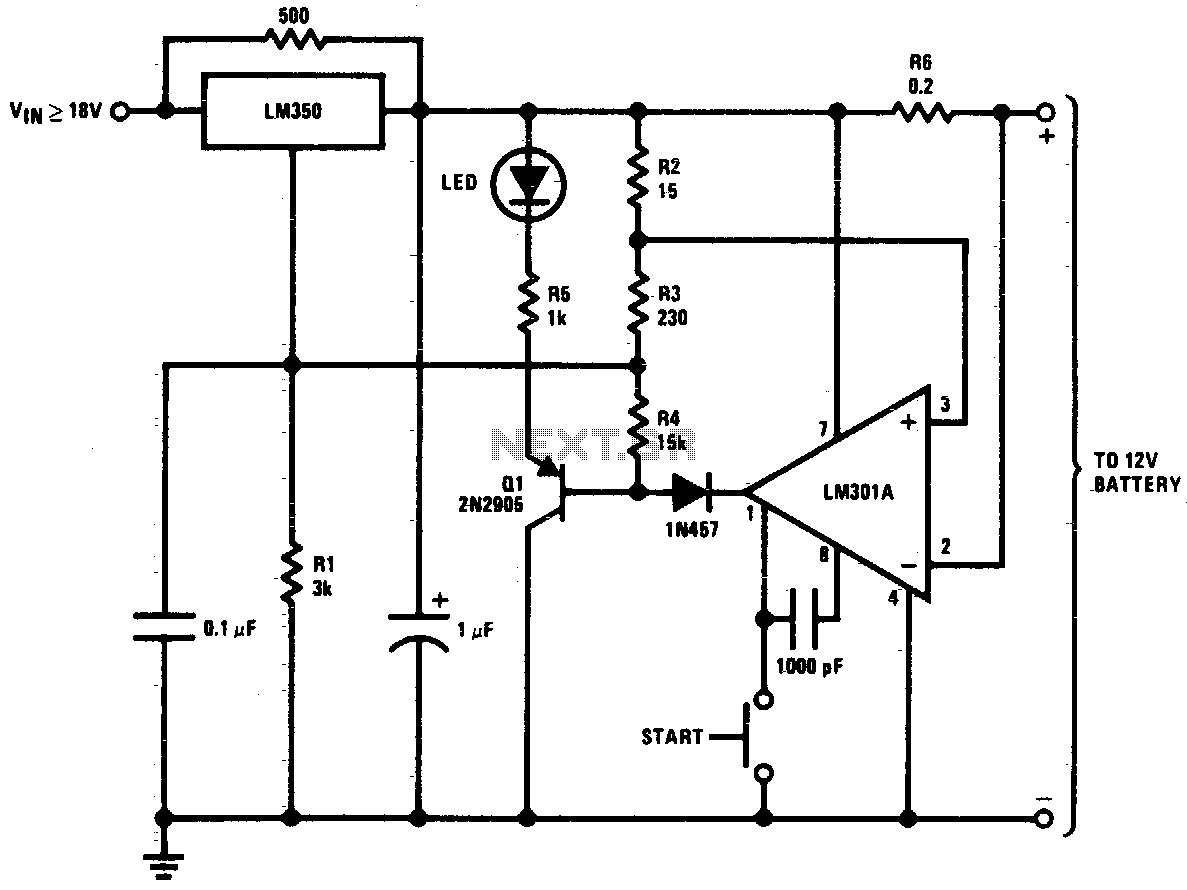
This circuit is a high-performance charger for gelled electrolyte lead-acid batteries. The charger quickly recharges the battery and automatically shuts off when it reaches full charge. Initially, the charging current is limited to 2A. As the battery voltage rises,...
This schematic illustrates a simple DIY solar cell phone or USB charger circuit. It is designed to charge any device that can be powered from a computer USB port, such as MP3 players, cell phones, and iPhones. The circuit...
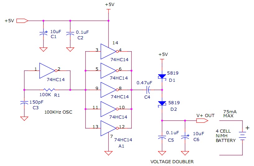
The circuit described will trickle charge a four-cell pack of AA or AAA NiMH batteries. It draws current from the +5V available from a USB connection and supplies approximately 70mA of current to the battery. This current level is...
A low-cost solution for charging both NiCd and NiMH batteries is presented. The circuit diagram illustrates a universal charger designed for these battery types. The circuit for the low-cost universal charger for NiCd and NiMH batteries typically incorporates several key...
This 24V to 36V linear battery charger is long overdue. While this is an old circuit technique, it is optimized for charging higher voltage lead-acid batteries. The 24V to 36V linear battery charger is designed to provide a stable charging...