
Ni-Cd Battery Charger Super Fast Circuit

The circuit utilizes the MAX 712 integrated circuit, which is specifically designed for charging Ni-Cd batteries efficiently. The MAX 712 features a precision voltage regulation system that ensures optimal charging of the batteries while preventing overcharging, which can lead to battery damage. The charging current of 300 mA is suitable for standard Ni-Cd batteries, allowing for a rapid charge cycle while maintaining battery health.
The circuit typically includes additional components such as resistors, capacitors, and diodes to support the functionality of the MAX 712. The input voltage is usually supplied from a transformer or a wall adapter, which is then rectified and filtered to provide a stable DC voltage to the charging circuit.
The MAX 712 monitors the battery voltage and adjusts the charging current accordingly, ensuring that the battery is charged to its full capacity without exceeding safe voltage limits. Furthermore, a temperature sensor may be integrated into the circuit to provide additional protection by interrupting the charging process if the battery temperature exceeds a predetermined threshold.
For practical implementation, it is essential to follow the manufacturer's guidelines for component selection and PCB layout to minimize noise and interference, which can affect charging efficiency. Overall, this circuit design offers a robust solution for fast charging of Ni-Cd batteries, making it suitable for various applications where quick battery turnaround is necessary.The following circuit shows about Ni-Cd Battery Charger Super Fast Circuit. Features: based on the IC MAX 712, Ni-Cd battery at 3oomA, charging .. 🔗 External reference
Related Circuits
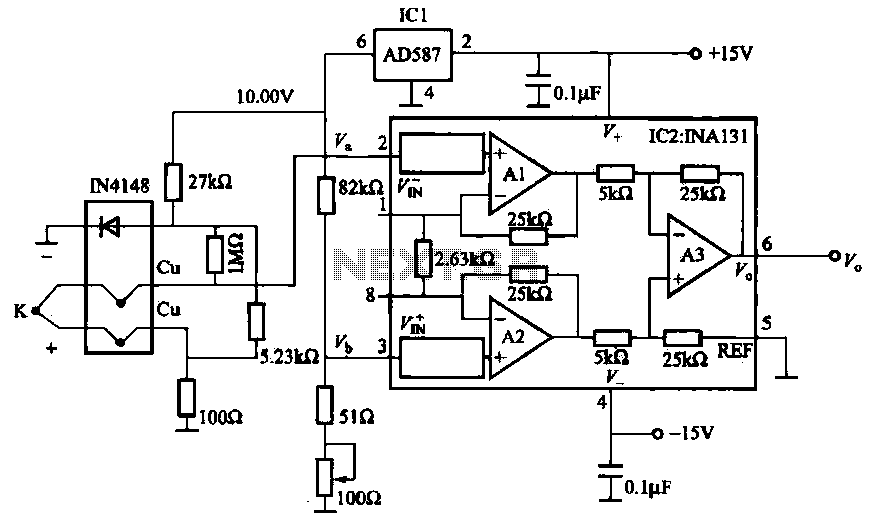
The AD587 is a precision voltage reference providing a 10 V output, generated using a 27 kΩ resistor along with a compensation diode (1N4148) and a thermocouple. This setup connects to the VI + N terminal of a differential...
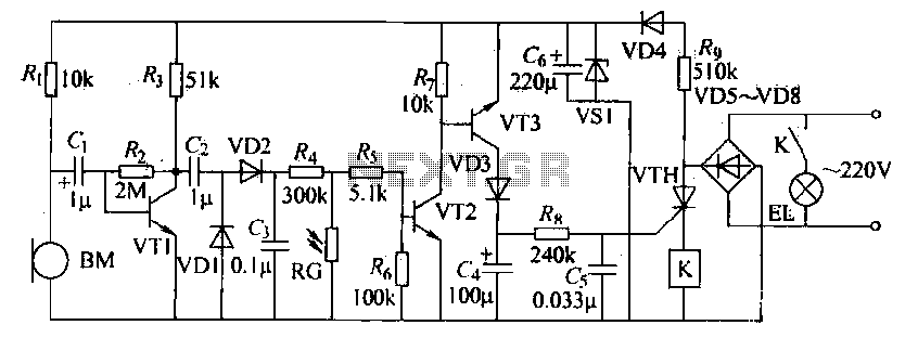
The voice circuits discussed in this section operate such that during daylight or in bright conditions, the voice-activated switch remains off, preventing the lamp from lighting. Conversely, in low-light conditions or at night, the sound control switch is activated....
This project involves a ding-dong doorbell circuit utilizing the 555 Integrated Circuit (IC). In a previous article, a simple doorbell circuit using the UM66 IC, a CMOS three-terminal melody IC, was discussed. The current circuit employs the NE555 IC...
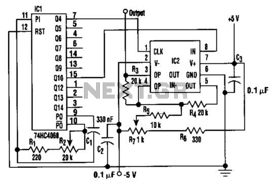
In this circuit, a square wave is filtered using a high-order low-pass filter designed to eliminate most harmonics of the waveform at a -3 dB frequency. Consequently, the output of the filter is a fundamental sine wave. This technique...

The modification of the differential circuit is illustrated. In Figure A1, an integrator is depicted, and the output is presented. The circuit modification involves integrating the differential circuit with an integrator component, which plays a crucial role in signal processing...
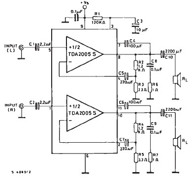
The TDA2005 car audio amplifier circuit is specifically designed for use in devices such as car radios, CD players, and similar equipment. This amplifier is based on the TDA2005 audio integrated circuit (IC), capable of delivering a maximum output...