
Voice remote control switch circuit

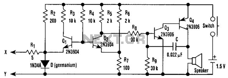
The circuit is illustrated in Figure 18-26. The microphone, along with components VT1, R1 through R3, and C, forms the sound amplification path. To achieve a higher sensitivity, a transistor with a gain greater than 100 should be used for VT1, and a high-sensitivity microphone is recommended. The power output should not be too low to avoid intermittent oscillation in the circuit. Components G, VD1, VD2, and C3 make up the rectifying circuit, converting the audio signal into a DC control voltage. The light control circuit is formed by R4, Rs, and a photosensitive resistor (R). When light strikes RG, its resistance decreases, resulting in a significant attenuation of the DC control voltage, which turns off VT2.
The electronic switch is composed of VT2, VT3, R, and VD3. Typically, in the presence of light, VT2 and VT3 are off, causing C4 to have no voltage, which keeps the thyristor VTH off, preventing the HL bulb from lighting. When VTH is off, a high DC voltage passes through R9 and VD4, charging C6 until it reaches 12V, at which point VSI breaks down, ensuring that the voltage across C6 does not exceed 15V. In the absence of light on RG, its resistance is high, leading to a smaller attenuation of the DC control voltage, which turns on VT2 and VT3, and also activates VD3.
The capacitor C5 begins to charge, causing the voltage to rise slowly. This voltage is applied to the control gate electrode of the thyristor VTH through the DC trigger voltage from C4. When VTH is activated, the relay coil K is energized, closing the normally open relay contacts and lighting the bulb EL. The duration for which the bulb remains lit is determined by the components in C4, with a specified duration of approximately 40 seconds before the lights turn off. Capacitor G serves as an interference capacitor to minimize flickering of the light bulb.
For component selection, transistors VT1 and VT2 should be 9014, while VT3 should be a 9012. The selection for VTH is a unidirectional thyristor rated at 100-8. Diodes VD1 through VD3 should be 1N4148, while VD4 should be a 1N4001 diode. Diodes VD5 to VD8 should be 1N4004. It is essential to use a high-sensitivity microphone along with the other components as shown in the schematic.Voice circuits described in this section, during the day or in brighter, voice-activated switch is turned off, the lamp does not light. At night or in low light, sound control switch is pre-working state. When someone after the nearby switch, footsteps, voices, clapping can start the voice switch, lights, delay after 40--50s, voice switches automatically turn off lights off. (1) works the voice switch circuit by the microphone BM, sound amplifier, a half-wave rectifier, light control, electronic switch, delay and AC switch circuit section 7.
The circuit shown in Figure 18-26. Microphone and VT1, R. ~ R3, C. Composition electrical sound amplification path. In order to obtain higher sensitivity value VT1 port should be used more than 100. The microphone also use high sensitivity. Po should not be too small, otherwise it is prone to intermittent oscillation circuit. G, VD1 and VD2, C3 constitute a rectifying circuit, an audio signal into a DC control voltage. R4, Rs and photosensitive resistance R (;. Composed of light control circuit when light is irradiated on the RG, its resistance becomes smaller, the DC control voltage attenuation large, VT2 off. VT2, VT3 and R ,, VD3 composed of electronic switches. usually, that is when there is light, VT2, VT3 cutoff .C4 no voltage on one-way thyristor VTH off, HL bulb does not light.
when VFH off, DC high voltage through R9, after VD4 buck added Cf upper end of the C6 charge when charge to 12V after, VSI breakdown, ensure the C6, the voltage does not exceed 15V. when there is no light shines on the RG, RG resistance is large, the DC control voltage attenuation is small .VT2, VT3 conduction, VD3 also turned on.
G, C5 starts charging voltage slowly rising wind, consisting of 0 and a one-way delay with thyristor vs AC switch .C4 by Ra DC trigger voltage VTH is applied to the control gate electrode, VTH is turned on, the relay coil K was electric, string EL branch normally open relay contacts K is turned on, the lamp EL ruffian light bulb lit the length of time by the C4, Yan parameter determining components of value, according to plans given in the bulb after the light for about 40s, RRHA & stop lights off .G as interference capacitors, except for a little light bulb flickering i (2) components selection VT1, VT2 are selected 9014 transistor, VT3 selection transistor 9012, to which the VT1 selection J;. B 100 VTH selection 100-8 unidirectional thyristor .VD1-VD3 made of 1N4148 diode, VD4 selects 1N4001 diode glance, VD5 ~ VD8 selected with 1N4004 diode to use high-sensitivity microphone, the other components in FIG.
Related Circuits
The LM1036 is a DC-controlled circuit designed for managing tone (bass and treble), volume, and balance functions in stereo applications, including car radios, televisions, and audio systems. Component: . The LM1036 integrates multiple audio control functionalities into a single chip,...
This circuit is a conventional Pierce type oscillator that utilizes a JFET. It operates with fundamental mode crystals and exhibits good performance and reliability when a low noise JFET is employed. The feedback is regulated by the capacitance of...
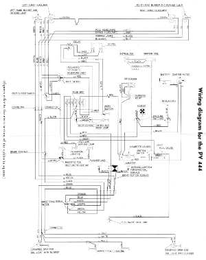
The following circuit illustrates the wiring diagram for the Volvo PV444, a vintage car electrical circuit. It provides an electrical understanding of this uni-body vehicle. The Volvo PV444 wiring diagram serves as a crucial reference for understanding the electrical system...
This document details a dual-axis stepper motor controller design and printed circuit board for an equatorial mount. Acknowledgment is given to Bill Prewitt for his assistance in creating this webpage. An encapsulated PostScript file containing the artwork for both...

This design circuit illustrates an LM1893 power line modem circuit. It is utilized to transfer information between remote locations using the power mains. The circuit employs the LM1893, which functions as a power line interface for half-duplex (bi-directional) communication...
This electronic pressure gauge utilizes a Wheatstone bridge-type pressure sensor to drive a 3 A digit A/D converter and a display. IC1 is a quad op-amp that interfaces the bridge sensor to the A/D converter. R16 allows for zero...