
Nicad Battery Charger circuit

The circuit operates by employing the BD140 transistor to regulate the charging current delivered to the load. The 1N4148 diodes serve as a reference voltage source, establishing a stable voltage level that is necessary for the proper biasing of the transistor. This configuration ensures that the charging current remains constant, regardless of variations in the load or supply voltage.
In this design, the base-emitter junction of the BD140 is activated by the voltage drop across the two 1N4148 diodes, which typically amounts to approximately 1.4V when forward-biased. This biasing allows the transistor to operate in its active region, maintaining a constant current output. The output current can be adjusted by changing the value of the resistor connected to the emitter of the BD140, thereby allowing for flexibility in the charging current based on the specific requirements of the application.
The overall circuit is efficient and straightforward, making it suitable for various low-power charging applications. It is important to ensure that the transistor's maximum ratings are not exceeded during operation, and appropriate heat sinking may be required depending on the load conditions. Additionally, the choice of diodes and their placement within the circuit can affect the overall performance and stability of the charger.his simple charger uses a single transistor as a constant current source. The voltage across the pair of 1N4148 diodes biases the base of the BD140 medium power transistor.. 🔗 External reference
Related Circuits
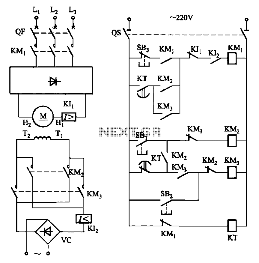
The circuit depicted in Figure 3-193 illustrates a separately excited DC motor. The brake circuit is not activated; therefore, positive reversals occur alternately using a delay action relay, ensuring that the motor reverses direction after coming to a stop. The...
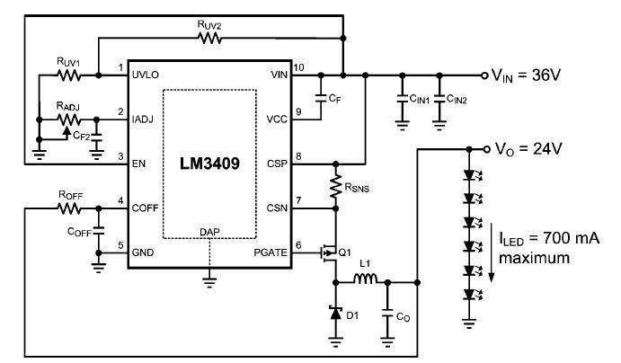
This dimming-controlled LED driver electronic circuit requires an input voltage of 36 volts and will provide an output voltage of 24 volts at a maximum current of 700 mA. The described dimming-controlled LED driver circuit is designed to efficiently convert...
The circuit consists of two differential amplifier transistors configured with a voltage dividing type bias circuit, measuring the resistance of four arms in a bridge configuration. The product includes a platinum resistance sensor, which exhibits an increase in resistance...
An attenuator is essential for anyone needing to reduce the amplitudes of RF signals in a controlled manner. While linearly adjustable attenuation networks using specialized PIN diodes are available, they necessitate complex control circuitry. A more straightforward solution is...
LED brightness control circuit: A simple circuit can be used to control the brightness level of an LED display. The LED brightness control circuit is designed to adjust the illumination level of an LED display according to user preferences or...

Designed to power a low-frequency subwoofer speaker system, the amplifier can deliver up to 100 W into an 8-ohm load. The OPA541BM operational amplifier, produced by Burr-Brown Corporation, necessitates heatsinking for optimal performance. Additionally, the design incorporates a damping...