
Separately excited DC motor reversing circuit

The schematic involves a separately excited DC motor, which is powered by an external voltage source that is independent of the armature circuit. This configuration allows for better control over the motor speed and torque.
In the circuit, a relay is employed to manage the motor's operation. The delay action relay is crucial for controlling the timing of the motor's reversal. When the motor is commanded to stop, the relay introduces a predefined delay before reversing the motor's direction. This delay is necessary to allow the motor to come to a complete stop before engaging the opposite polarity, thereby preventing mechanical stress and potential damage.
The braking mechanism is passive in this circuit, meaning that it does not actively apply a braking force but relies on the natural inertia of the motor and the load it drives. This approach can be beneficial in applications where rapid deceleration is not critical, but it requires careful timing to ensure smooth transitions between forward and reverse operations.
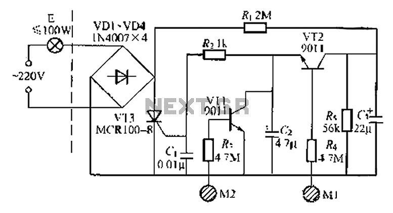
Overall, the circuit design emphasizes the importance of timing and control in motor applications, particularly in scenarios where alternating direction is required. The use of a separately excited motor combined with a delay action relay provides a reliable method for achieving controlled reversals. Circuit shown in Figure 3-193. Motor is separately excited DC motor. The brake circuit does not take measures, so the positive reversals alternately using delay action time rel ay KT ensure after stopping to reverse the motor started.
Related Circuits
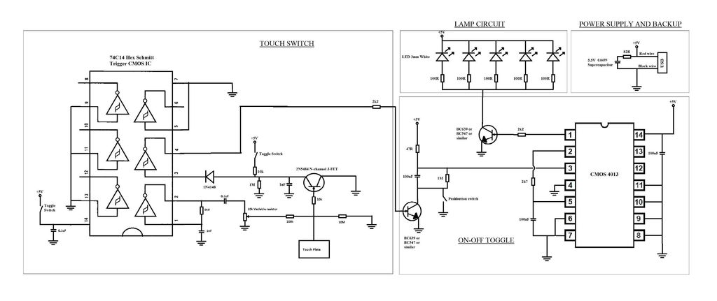
A touch switch for a USB-powered desk lamp is malfunctioning. The circuit diagram, layout, and pictures are provided below. The design incorporates circuits sourced from two websites, specifically the fourth circuit. The output of the touch switch is connected...
The simple pressure sensor alarm is constructed using a few inexpensive and readily available components. The operation of this circuit is straightforward and self-explanatory. When powered by a 9V compact battery, the active piezo sounder at the output of...
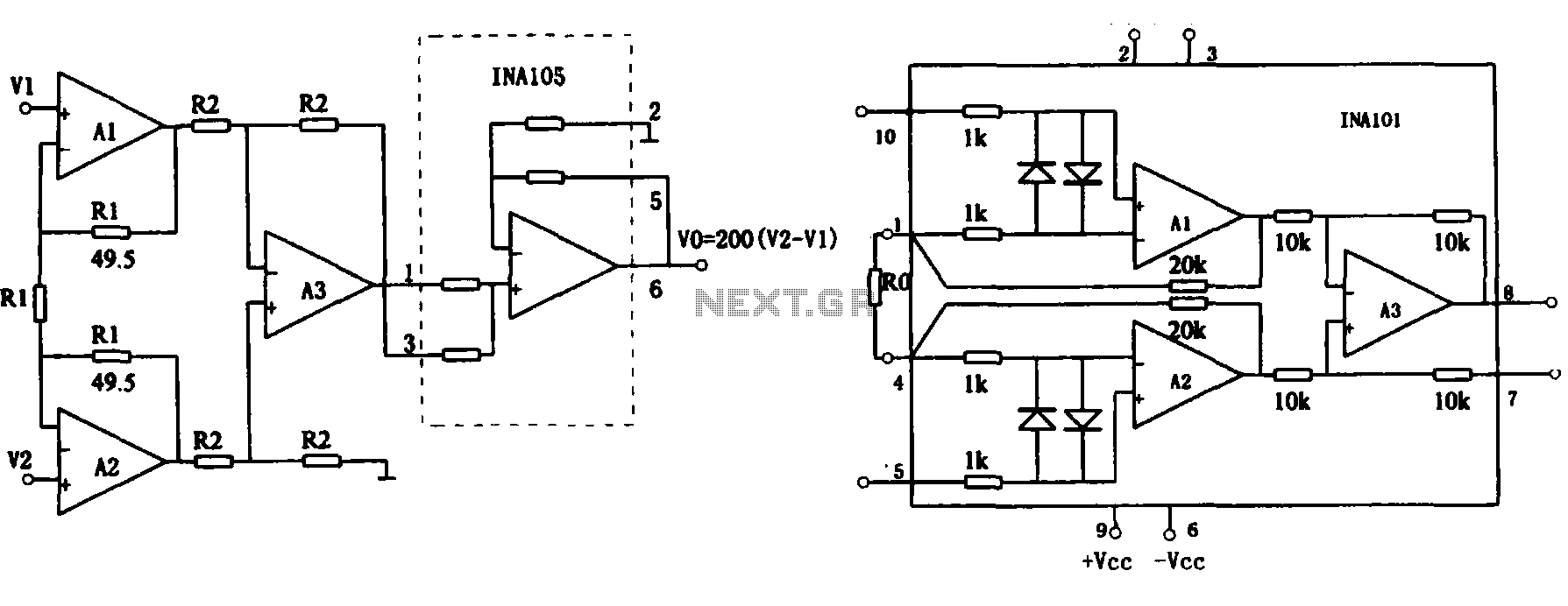
This document describes the extended common mode input voltage range of an instrument amplifier circuit. The circuit consists of three precision instrument amplifiers, A1, A2, and A3, which can be INA101 or INA102 models. The figure illustrates that A1,...
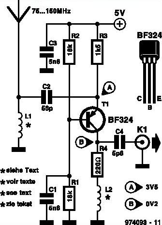
This inexpensive FM radio receiver antenna booster utilizes the BF324 TO92 style PNP transistor in a grounded-base configuration. The circuit can be employed as a... The FM radio receiver antenna booster circuit is designed to enhance the reception capabilities of...
This project outlines the construction of a Brushed Motor Electronic Speed Controller (ESC) for cars and boats using a Microchip 12F675 PIC and a limited number of standard components. This ESC is a revised version of an earlier aircraft...
A good performance is achieved with a two-wire connection for a double touch switch that can function even if there is a break in the left part of the line. This switch is designed for general lighting control, such...