
0-44dB RF Attenuator circuit with RF 2420

The RF 2420 integrated circuit (IC) serves as a versatile and efficient solution for RF signal attenuation in various applications, including cable television systems. Its design leverages gallium-arsenide (GaAs) technology, which is known for high-frequency performance and low noise characteristics, making it suitable for a broad range of RF applications. The IC's frequency range of 1 MHz to 950 MHz allows it to handle signals commonly found in television broadcasts, ensuring that signal integrity is maintained while reducing amplitude as needed.
The attenuation capability of the RF 2420 is notable, with a range from 0 to 44 dB in 2-dB steps. This granularity allows for precise control over signal levels, which is particularly beneficial in environments where signal strength must be meticulously managed to prevent distortion or interference. The insertion loss of 4 dB, while a consideration, is standard for such devices and is accounted for in the overall design and application of the attenuator.
Control of the RF 2420 is facilitated through a set of 5 TTL inputs, which provide a straightforward method for users to set the desired attenuation levels. The specified voltage levels for the control signals ensure compatibility with standard digital logic levels, simplifying integration into existing systems. The operational voltage range of +3 V to +6 V and the typical current consumption of 4 mA indicate that the RF 2420 is energy-efficient, making it suitable for battery-powered applications or systems where power consumption is a critical factor.
The inclusion of a power-down mode is advantageous, allowing for further energy savings when the attenuator is not in use. By disconnecting power from the bussed VDD- pins, the current consumption can be significantly reduced to 0.8 mA, enhancing the overall efficiency of the system.
In terms of external components, the RF 2420 requires only decoupling capacitors, which simplifies the design and reduces the footprint of the circuit. The choice of coupling capacitors at the input and output plays a crucial role in defining the lower frequency operating limit, which should be carefully selected based on the specific application requirements. The IC is designed for 50-ohm operation, a standard for RF applications, but it also provides flexibility for use with 75-ohm systems, accommodating a variety of cable types while acknowledging a minor increase in reflections.
Finally, the RF 2420 is packaged in a 16-pin SOP-16 SMD format, which is compact and suitable for surface mount technology, facilitating easy integration into modern electronic designs. The availability of the data sheet at www.rfmd.com provides comprehensive technical details and specifications for engineers and designers seeking to implement this IC in their projects.Anyone who has to reduce the amplitudes of RF signals in a controlled manner needs an attenuator. Linearly adjustable attenuation networks using special PIN diodes are available for this, but they require quite intricate control circuitry. A simpler solution is to use an integrated attenuator that can be switched in steps. The RF 2420 is an IC bui lt using gallium-arsenide (GaAs) technology, which works in the frequency range between 1 MHz and 950 MHz. It can thus be used as an attenuator for cable television signals, for example. The attenuation can be set between 0 and 44 dB in 2-dB steps. An insertion loss of 4 dB must also be taken into account. This base attenuation can be measured in the 0-dB setting, and it forms the reference point for switchable attenuation networks that provide 2, 4, 8, 10 and 20 dB of attenuation.
These are all controlled by a set of 5 TTL inputs. The control signals must have Low levels below 0. 3 V and High levels of at least +2. 5 V. The RF 2420 works with a supply voltage between +3 V and +6 V, with a typical current consumption of 4 mA. A power-down mode, in which the current consumption drops to 0. 8 mA, can be activated by removing power from the bussed VDD- pins. The sample circuit diagram for the RF 2420 shows that the only external components that are needed are decoupling capacitors.
The coupling capacitors at the input and output determine the lower operating frequency limit. The table lists possible capacitor values. The input and output are matched to 50-ohm operation, but they can also be used with 75-ohm cables with a small increase in re‚ections. The RF 2420 is available in a 16-pin SOP-16 SMD package. Its data sheet can be found at ww. rfmd. com. 🔗 External reference
Related Circuits
The sensor operates on the principle that at high temperatures (200 to 800 °F), the temperature of the sensor varies with the thermal conductivity of gas, leading to changes in the resistance of the platinum resistor wire. In the...
The 555 circuit can be re-triggered if the input is held low for a duration longer than the output pulse. To prevent this from occurring, an additional timing circuit has been incorporated, consisting of a 1 Megohm resistor and...

The circuit for the Digital Tachometer/RPM Counter consists of a few components. They should be connected according to the provided circuit diagram. The PIC used is on a demonstration board, meaning the clock, power, and ground pins are already...
If you want to try a higher voltage with your pedals, try this simple and easy voltage doubler circuit which uses an ICL7660 CMOS Voltage Converter Chip. I have found that JFETs such as the J201 sound much better...
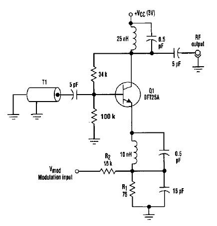
This varactorless high-frequency modulator electronic project must be powered by a simple DC 3-volt power source, such as a 3-volt battery. Traditionally, high-frequency oscillators are frequency-modulated using a varactor. However, varactors typically require a significant voltage change to achieve...
This is the unedited version of the article "Improved Anode-Circuit Parasitic-Suppression For Modern Amplifier-Tubes," which was published on page 36 of the October 1988 issue of QST. A subsequent discussion on this topic appeared in the September and October...