
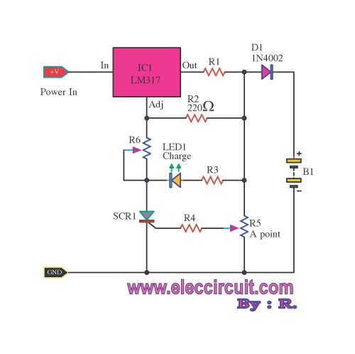
NiCads charger

* the voltage definition,
* the integrator,
* the current booster, and
* the foldover. The schematic is drawn so that higher voltages are toward the top and lower voltages are towards the bottom. D1 is a voltage reference, LM385BZ-2.5, that maintains a drop of 2.5 volts across its leads. Since B will be close to ground, there should be about 1.5 volts across R1 and about 0.8 mA of current, which is enough to keep D1 alive. The schematic above shows the overall control loop. The glowplug is represented by R9. Notice there are 2 connections at each end of the plug. The heavy lines represent heavy wire that carries the current to/from the plug. The thinner
The driver circuit is designed to control the operation of a glowplug, which is a resistive heating element used in diesel engines to aid cold starting. The circuit is divided into four distinct sections that each serve a specific function in the overall operation.
The voltage definition section utilizes the LM385BZ-2.5 voltage reference diode (D1), which ensures a stable 2.5V reference voltage necessary for the proper functioning of the circuit. This voltage reference is critical as it sets the baseline for the other components in the circuit. The resistor R1 is connected in series with the voltage reference to limit the current flowing through D1, ensuring that it operates within its specified range. The expected voltage drop across R1 is approximately 1.5V, leading to a current of around 0.8 mA, which is sufficient to maintain the operation of the voltage reference.
The integrator section processes the input signal and provides necessary feedback to maintain the desired operating conditions for the glowplug. This section typically includes an operational amplifier configured to integrate the voltage over time, ensuring that the output is a smooth, continuous signal rather than a pulsed one.
The current booster section is responsible for amplifying the current supplied to the glowplug. Given that the glowplug requires a significant amount of current to reach its operating temperature, this section is designed to handle higher currents without overheating or failing. It may include transistors or MOSFETs configured to switch larger currents while being controlled by the lower current signals from the previous sections.
Lastly, the foldover section serves as a protection mechanism, preventing the circuit from exceeding safe operational limits. It monitors the output current and voltage, ensuring that they remain within specified thresholds. If the current approaches unsafe levels, the foldover circuit will reduce the output, protecting both the glowplug and the driver circuit from damage.
The overall schematic is organized with higher voltage connections at the top and lower voltage connections at the bottom, which aids in understanding the flow of current through the circuit. The glowplug, represented by R9, is connected via heavy gauge wires, indicated by the thick lines in the schematic, to handle the significant current required for operation. The thinner lines represent other connections that may carry lower currents or signals. The careful design and arrangement of these components ensure the effective and safe operation of the glowplug driver circuit.The driver circuit (see the complete schematic) has 4 main sections: * the voltage definition, * the integrator, * the current booster, and * the foldover. The schematic is drawn so that higher voltages are toward the top and lower voltages are towards the bottom.
D1 is a voltage reference, LM385BZ-2.5 (you can get all these parts from Allied Electronics), that maintains a drop of 2.5 volts across its leads. Since B will be close to ground, there should be about 1.5 volts across R1 and about 0.8 mA of current, which is enough to keep D1 alive.
The (somewhat abstract) schematic above shows the overall control loop. The glowplug is represented by R9. Notice there are 2 connections at each end of the plug. The heavy lines represent heavy wire that carries the current to/from the plug. The thinner 🔗 External reference
Related Circuits
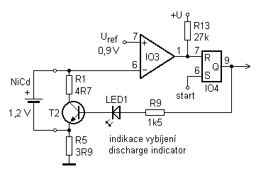
If you use different batteries with actual capacity, with different self-discharge rate of batteries from different manufacturers, you will perhaps throw further described charger. Because each cell can be discharged separately recharge, can be charged with varying articles carrying...
This battery charger circuit is regulated and adjustable, enabling it to charge most NiCAD batteries. It is suitable for single cells or multiple battery cells connected in series or parallel configurations. The maximum... This battery charger circuit is designed to...
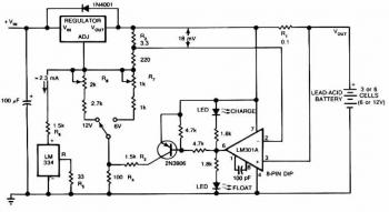
The following circuit illustrates a 1.5 V Lead-Acid Battery Charger Circuit Diagram. Features include a comparator output that controls the voltage regulator. The 1.5 V Lead-Acid Battery Charger Circuit is designed to efficiently charge lead-acid batteries while ensuring optimal voltage...
The lithium battery charger introduced in the example can charge a 6V lithium-ion battery in a constant current mode and switch to constant voltage charge mode when the battery voltage reaches 4.1V. The lithium battery charger circuit operates on...
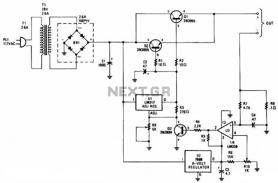
When building a lead-acid battery charger for a 6V or 12V battery, there are various methods available. One preferred option is the use of the IC LM317. The LM317 is a versatile adjustable voltage regulator that can be effectively utilized...
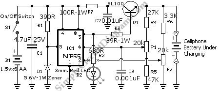
While traveling, charging a mobile phone can be a significant challenge due to the general inaccessibility of power supply sources, leading to the risk of the battery depleting. To address the issue of mobile phone battery depletion during travel, a...