
2.5 V Lead-Acid Battery Charger

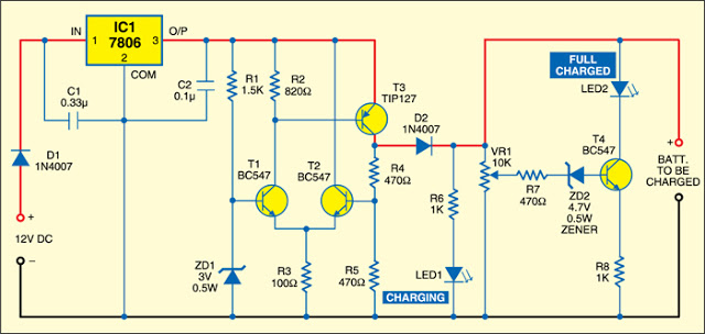
The 1.5 V Lead-Acid Battery Charger Circuit is designed to efficiently charge lead-acid batteries while ensuring optimal voltage regulation and protection against overcharging. The circuit utilizes a voltage comparator that monitors the battery voltage and adjusts the output of the voltage regulator accordingly.
In this configuration, the voltage comparator is typically set up with a reference voltage that corresponds to the fully charged state of the battery. When the battery voltage drops below this reference level, the comparator activates the voltage regulator, allowing current to flow into the battery for charging. Conversely, once the battery reaches the desired voltage threshold, the comparator's output will signal the regulator to cease charging, thereby preventing damage to the battery from overvoltage conditions.
Key components in this circuit may include a voltage regulator IC, such as the LM317, which can be adjusted to output the necessary charging voltage. Additionally, protection diodes can be incorporated to safeguard against reverse polarity and to prevent current from flowing back into the circuit when the power source is removed.
The circuit may also include filtering capacitors to stabilize the output voltage and ensure a smooth charging process. A current limiting resistor can be added in series with the output to control the charging current and further protect the battery.
Overall, this simple yet effective circuit design facilitates safe and reliable charging for 1.5 V lead-acid batteries, making it suitable for various applications where such battery technology is employed.The following circuit shows about 1.5 V Lead-Acid Battery Charger Circuit Diagram. Features: comparator s output controls the voltage regulator, .. 🔗 External reference
Related Circuits
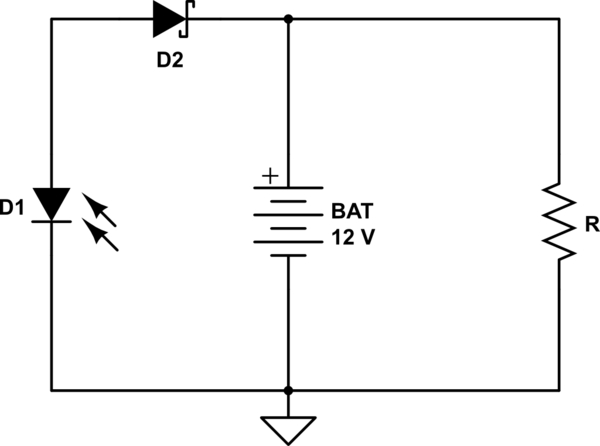
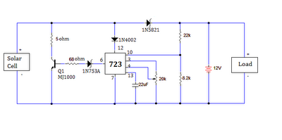
A 12V battery is charged using a solar panel. When the battery reaches 12V, the solar panel is disconnected from the battery, and the load is connected to the battery. The solar panel is reconnected to the battery when...
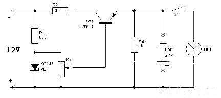
The schematic diagram originates from a circuit designed for a Car Lamp Charger power supply. The diagram illustrates a Car Lamp Charger circuit, which features a unique characteristic: the battery will not recharge. This circuit is integrated into a...
The circuit presented is an integrated circuit (IC) controlled emergency light. Its key features include automatic activation of the light during mains failure and a battery charger equipped with overcharge protection. In the absence of mains power, relay RL2...
There is no need to be disappointed the next time your digital camera displays a low battery indication during a picnic trip. Simply connect this digital camera adapter to the cigarette lighter outlet of your car and link the...
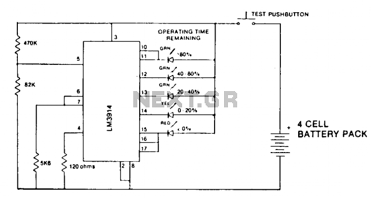
A state-of-charge indication of a sloping-voltage discharge can be utilized as a state-of-charge indicator. A typical voltage comparator circuit that provides a visual indication of the state of charge is presented. Components identified are for a 4-cell input voltage...
The ultimate source of energy is the Sun. It is possible to generate current from sunlight using solar panels. These panels convert light energy into electrical energy. A solar panel consists of a number of solar cells, which produce...