
NiCd Battery Charger Circuit

The NiCd battery charger circuit is designed to accommodate both 6V and 12V NiCad batteries, making it versatile for various applications. The core component of this circuit is a transformer, which is responsible for stepping down the AC voltage from the mains supply to a suitable level for charging the batteries. The transformer is rated to deliver a current in the range of 4 to 5 A, ensuring that it can efficiently supply the necessary power for charging.
The circuit typically includes a rectifier, which converts the AC output from the transformer into DC, suitable for charging the batteries. This is often achieved using a bridge rectifier configuration, which allows for full-wave rectification, improving the efficiency of the charging process. Following the rectification stage, a smoothing capacitor is used to filter out any ripple voltage, providing a stable DC output.
To prevent overcharging, the circuit may incorporate a charging control mechanism, such as a voltage regulator or a timer circuit. This ensures that the batteries are charged to their optimal voltage and prevents damage due to excessive charging. Additionally, the schematic may include protection diodes to prevent reverse current flow, which can occur when the batteries are disconnected from the charger.
The design should also consider thermal management, as charging can generate heat within the components. Adequate heat sinking for the rectifier and any voltage regulation components is essential to maintain performance and reliability.
Overall, this NiCd battery charger circuit schematic is a practical solution for charging both 6V and 12V NiCad batteries, with a focus on efficiency, safety, and reliability.This NiCd baterry charger circuit schematic can charge 6 volts as well as 12 volts NiCad batteries. It uses a transformer which can deliver 4 to 5 A curren.. 🔗 External reference
Related Circuits
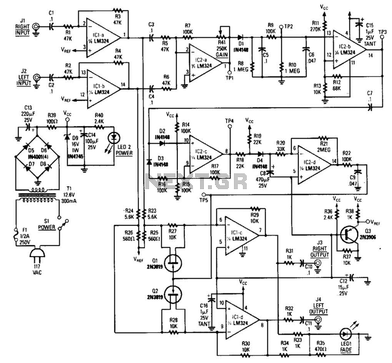
The LR inputs are summed, processed, and then drive a comparator. This comparator detects levels and generates transitions when audio inputs exceed or fall below predetermined thresholds. The frequency of these transitions, which correspond to rapid volume changes, is...
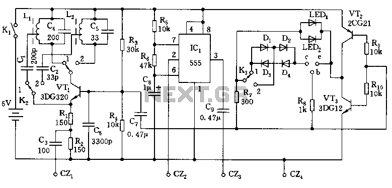
The overhaul includes features such as online judge diodes, the ability to test whether transistors are functioning properly, and the capability to assess TTL logic levels or high impedance states. It can output signals at 37 MHz, bar television...
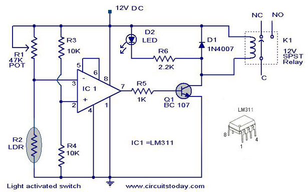
A simple light-activated switch circuit diagram utilizes the National Semiconductor comparator IC LM311 and a light-dependent resistor (LDR). The circuit functions as a voltage comparator, with the non-inverting input of IC1 receiving a reference voltage of 6V through resistors...
This is a three-band equalizer circuit, specifically a tone control circuit that utilizes a single operational amplifier (op-amp) and features three adjustable frequency ranges: bass, midrange, and treble. The three-band equalizer circuit employs an operational amplifier to achieve tone control...
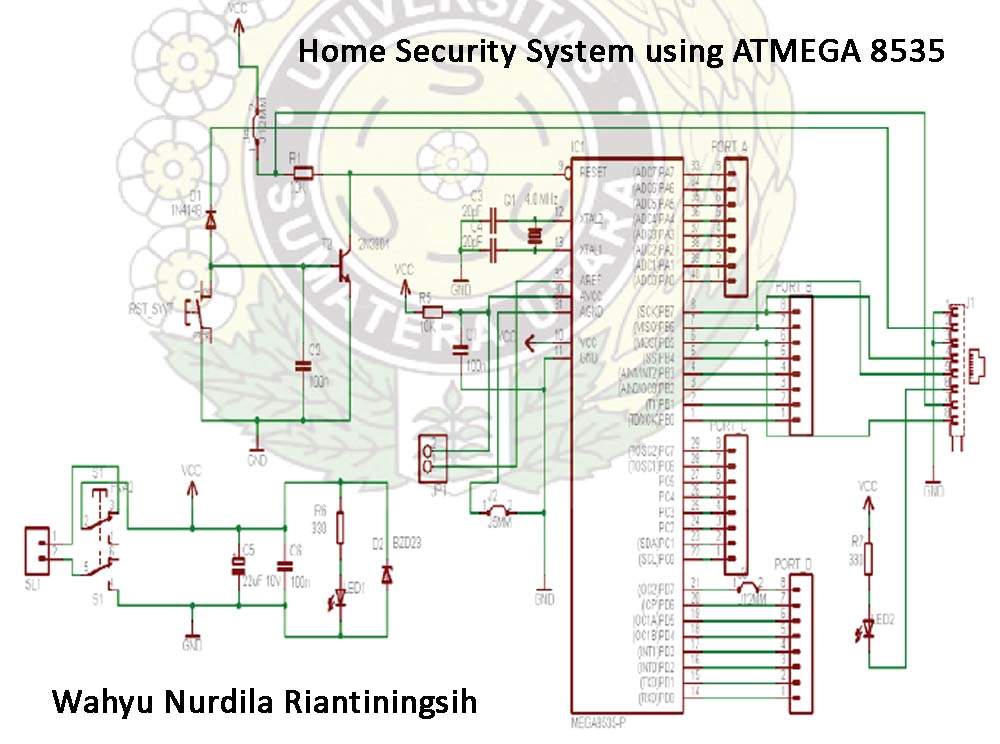
The Atmega 8535 Color Conversion to Frequency project utilizes instrumentation technology to recognize colors, also known as a color sensor, which is essential in various industrial applications. This sensor has multiple uses, ranging from the paint industry to satellite...
This circuit utilizes a standard loudspeaker, enabling it to function as a microphone. It allows for the use of an inexpensive loudspeaker in this capacity. Sound waves impacting the speaker cone result in variations in the voice coil. The...