
3 Band Equalizer Circuit
The three-band equalizer circuit employs an operational amplifier to achieve tone control across different frequency bands. The circuit typically consists of three separate filters, each designed to adjust the gain of a specific frequency range: low frequencies for bass, mid frequencies for midrange, and high frequencies for treble.
The implementation begins with the op-amp configured in a non-inverting amplifier setup, where the input audio signal is fed into the non-inverting terminal. Each band consists of a passive filter network that can be adjusted using potentiometers, allowing the user to boost or cut the desired frequency bands.
For the bass control, a low-pass filter is utilized, which allows frequencies below a certain cutoff to pass through while attenuating higher frequencies. Similarly, the midrange control is achieved using a band-pass filter that selectively amplifies mid frequencies while rejecting both lower and higher frequencies. The treble control employs a high-pass filter, allowing frequencies above a specific cutoff to pass through while attenuating lower frequencies.
The output of each filter is then summed together at the output of the op-amp, resulting in an audio signal that has been modified according to the settings of the three potentiometers. This circuit is widely used in audio applications for adjusting sound quality and tailoring the audio output to suit personal preferences or specific acoustic environments.
Careful component selection, including the values of resistors and capacitors in the filter networks, is crucial to achieving the desired frequency response. Additionally, power supply decoupling may be implemented to ensure stable operation of the op-amp, preventing noise and distortion in the audio signal. Overall, this three-band equalizer circuit provides a versatile and effective means of controlling audio frequency response in various applications.Here is 3 band equalizer circuit other. A tone control circuit made with a single op-amp and having three ranges, bass, middle and treble controls. Using a. 🔗 External reference
Related Circuits
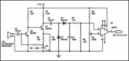
Ultrasonic receivers detect an ultrasonic signal emitted by an ultrasonic transmitter at a specific frequency. The received signal is filtered using a band-pass filter circuit that allows only the predetermined frequency range to pass. The output signal is then...
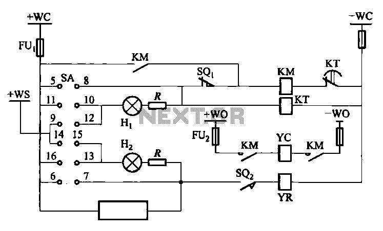
The DW10M de-excitation type switch is based on the DW10 automatic air circuit breaker, transitioning from normally open to normally closed contact. The models available include DW10M-200, DW10M-400, and DW10M-600. The control circuit for this type switch is illustrated...
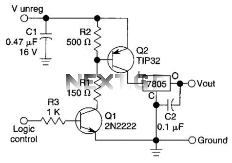
A logic level can control a 7805 regulator with this circuit. Q2 is a series switching transistor controlled by Q1. Q1 is turned on by a logic voltage to its base. This circuit utilizes a 7805 voltage regulator, which is...
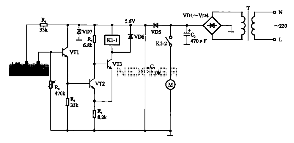
Automatic sprinkler control circuit. This circuit primarily consists of a humidity sensor, a detection signal amplifying circuit (including transistors VT1, VT2, and VT3), a power supply circuit (comprising a filter capacitor C2, a bridge conditioning circuit UR, and a...
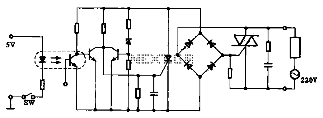
This application example illustrates a photovoltaic control circuit. In this circuit, the Triac functions as a solid-state relay, providing an AC power supply path to the load. It is designed to achieve high current control signals using a small...
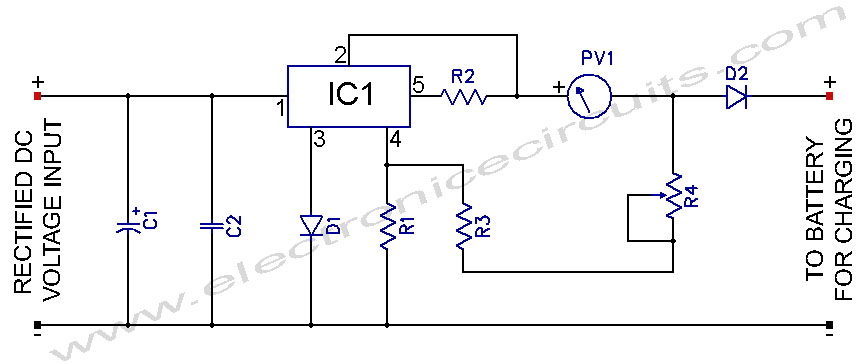
L200 12V Constant Voltage Battery Charger Circuit. This battery charger is based on the L200 regulator IC. The L200 is a five-pin adjustable voltage regulator. The L200 constant voltage battery charger circuit is designed to provide a stable 12V output...