
Low Cost Universal Battery Charger Schematic

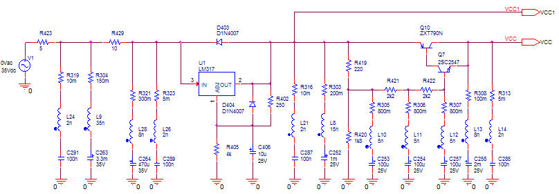
The schematic for the NiCd and NiMH battery charger typically includes a transformer, rectifier, and voltage regulation components to ensure a stable charging current. The transformer steps down the input AC voltage to a suitable level for charging. The rectifier, often a bridge rectifier configuration, converts the AC voltage to DC voltage, which is necessary for charging the battery.
The charging circuit may also incorporate a resistor to limit the charging current to the specified value of I (1/10 of the battery capacity). This resistor is crucial for preventing damage to the battery from excessive current. The use of a potentiometer can allow for fine-tuning of the charging current, accommodating batteries with different capacities.
Furthermore, a diode may be included in the circuit to prevent reverse current flow, which can occur when the charger is disconnected from the battery. This feature protects the charger and prolongs the lifespan of the battery.
For safety and efficiency, it is essential that the input voltage is adequately regulated and filtered to ensure that the charger operates within safe limits. The design should also consider thermal management, as charging can generate heat, which may affect the performance and safety of the components involved.
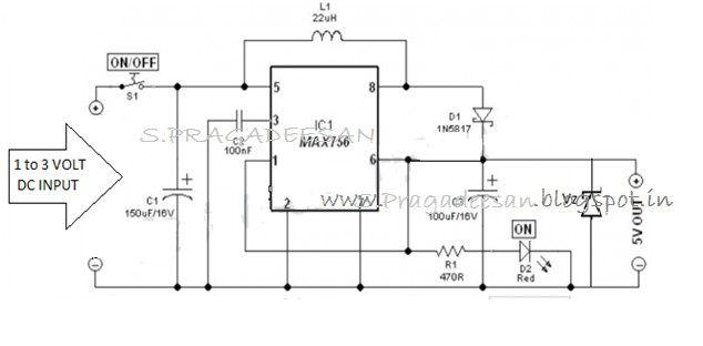
Overall, this simple NiCd and NiMH battery charger circuit is an effective solution for charging batteries efficiently while minimizing costs. It is suitable for hobbyists and applications where cost and simplicity are paramount.Here the simple and low cost NiCd and NiMH battery charger: Schematic diagram: Note: I is 1/10 of the batterys charging capacity. For example if battery has a rated capacity of 1700mA then ?=170. The input voltage must be at least 3 times.. 🔗 External reference
Related Circuits
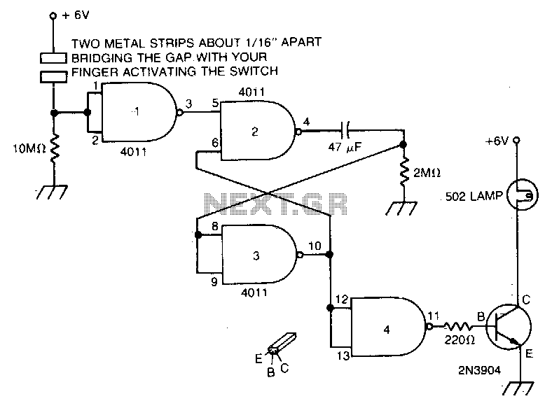
Touch the plate, and the light will turn on and remain on due to the 47 µF capacitor and the 2MΩ resistor for a duration determined by the timing resistor. The circuit described involves a touch-sensitive plate that activates a...
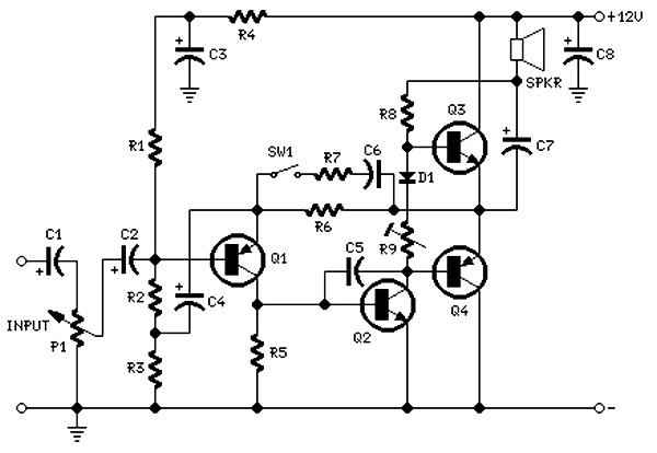
The circuit is intentionally designed using older type transistors to achieve harmonic distortion and to mitigate the challenges of sourcing high-quality components. The amplifiers can be easily powered by a plug-in wall transformer rated at 12V. When SW1 is...
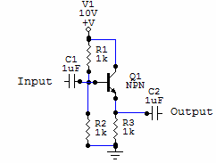
Two examples of the most common types of Voltage followers (buffers). You can find some theory behind them in our amplifier gain and buffer amplifier pages. This first circuit is a very simple one transistor voltage follower. Consists of...
Every innovation begins with a simple everyday problem, such as watching an IPL match on TV when suddenly the power goes out, prompting the search for an alternative way to watch via mobile network. Similarly, a frequent issue of...
This circuit is designed to flash a white LED using a supply voltage ranging from 2V to 6V, resulting in a very bright flash. The circuit operates at approximately 2mA, allowing the use of old batteries. When powered at...
The concept of distributed active RIAA correction and the use of negative feedback to linearize the input stage is appealing. However, the original design by Collin has significant flaws, including poor power supply rejection ratio (PSRR) in the input...