
nicd nimh battery charger circuit

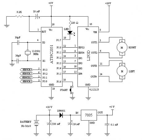
The circuit for the NiCd and NiMH battery charger is designed to be straightforward, allowing for the charging of multiple batteries simultaneously. The schematic typically includes a power supply, a charging control circuit, and battery connections.
The power supply can be a standard AC to DC adapter that provides the necessary voltage and current for charging. The charging control circuit often consists of a voltage regulator, which ensures that the output voltage remains stable and appropriate for charging NiCd and NiMH batteries.
A common configuration may include a series of resistors and diodes to manage the charging current and protect against reverse polarity. Additionally, a microcontroller or simple comparator circuit can be integrated to monitor the battery voltage and terminate charging once the batteries reach full charge, preventing overcharging and extending battery life.
Battery connections are typically made using a terminal block or soldered connections, allowing for easy attachment and detachment of the batteries. It is essential to ensure that the circuit is designed to handle the specific voltage and current ratings of the batteries being charged, with appropriate safety features such as fuses or thermal cutoffs to prevent overheating.
In summary, this charger circuit is a practical solution for charging multiple NiCd and NiMH batteries, combining simplicity in design with effective charging capabilities. Proper attention to component selection and circuit layout is crucial for optimal performance and safety.Schematic and description of a simple and easy to built NiCd and Nimh battery charger circuit which is able to charge multiple NiCd and NiMH batteries. .. 🔗 External reference
Related Circuits
This device utilizes the MC145026/MC145027 encoding and decoding circuit along with the TDA1808/TDA1809 RF transmitter/receiver module. It can be operated flexibly within a range of 10 to 120 meters, allowing users to maintain the original external appearance and internal...

Digital Command Control (DCC) provides significant advantages over traditional DC analog control systems, primarily due to its simplified wiring. DCC enables the individual control of multiple locomotives on the layout without requiring electrical isolation of track sections. The main...
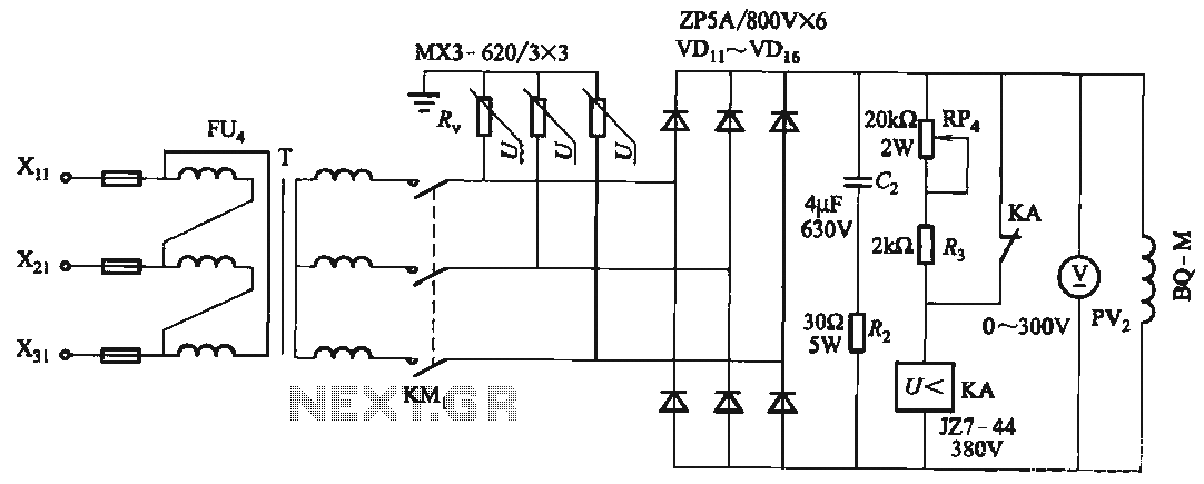
FIG T is the excitation transformer, R is a varistor, and there are rectifier diodes to protect against breakdowns from VDii to VD16; Rz and C2 provide resistive-capacitive protection. The circuit is designed to absorb voltage from the magnetic...
A minimum number of parts yields a compact switching converter that can provide sufficient voltage to drive white LEDs. The resulting lamp is much more efficient, in terms of lumen hours per pound of battery, than incandescent bulbs, and...
This compact circuit enables automatic recording of phone conversations. It connects to the phone line, the microphone input of a tape recorder, and the remote control jack of the recorder. The circuit detects the voltage level in the phone...
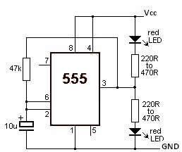
This LED flasher circuit utilizes the 555 timer integrated circuit (IC). The circuit diagram is straightforward and requires only a few external components. When operational, the red LEDs will flash sequentially at a predetermined frequency, similar to the indicators...