
Telephone line monitor circuit

This circuit utilizes a voltage sensing mechanism to monitor the phone line for activity. When a call is initiated, the voltage typically remains above 5 volts. However, once the call is in progress and the voltage drops to 5 volts or less, the circuit triggers the recording function. This is achieved through a combination of a voltage divider and a transistor switch, which activates the tape recorder.
The circuit can be designed with a simple NPN transistor as a switch, where the base is connected to the voltage divider that senses the phone line voltage. The collector of the transistor connects to the remote control jack of the tape recorder, allowing it to start recording when the transistor is activated. Additionally, a resistor-capacitor (RC) timing circuit may be employed to ensure that the recording starts smoothly without any initial noise or delay.
Powering the circuit can be accomplished using a small battery or a power supply connected to the tape recorder. Care should be taken to isolate the circuit from the phone line to prevent any interference or damage. Incorporating a diode for reverse polarity protection is advisable, ensuring the circuit remains safe from accidental connection errors.
Overall, this automatic recording circuit provides a practical solution for capturing phone conversations without manual intervention, making it a valuable tool for various applications such as interviews, meetings, or personal record-keeping.This nifty little circuit lets you record your phone conversations automatically. The device connects to the phone line, your tape recorder`s microphone input, and the recorder`s remote control jack. It senses the voltage in the phone line and begins recording when the line drops to 5 volts or less..
🔗 External reference
Related Circuits
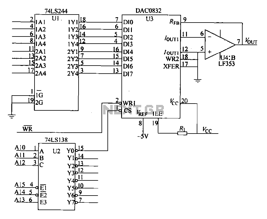
The DAC0832 is depicted in Figure 27-13 as a single-phase circuit connected to the 8086 CPU. The internal 8-bit data input of the DAC0832 must be interfaced with the CPU and the D/A converter interface circuits for data transmission,...

A simple 6-volt DC regulator circuit with a diagram and schematic using the 7806 IC, a positive voltage regulator. It serves as an elementary 6-volt, 1-ampere power supply circuit. The 7806 voltage regulator is a widely used integrated circuit that...
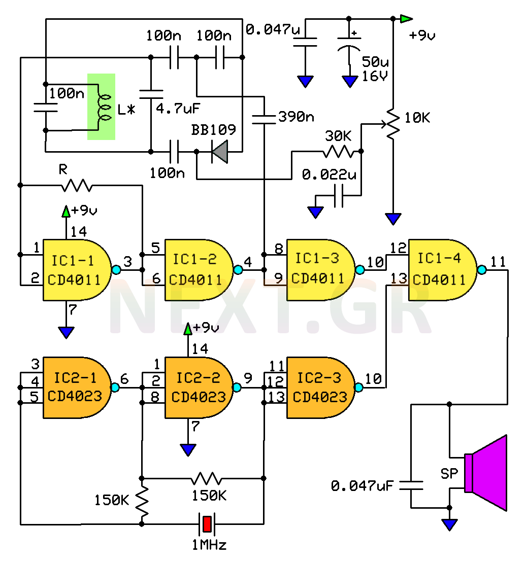
This circuit is a metal detector designed to detect large metallic objects at depths ranging from 2 to 3 meters, depending on the size of the object and the type of soil. The construction is straightforward, making it accessible...
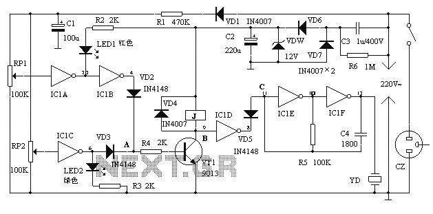
The alarm protection can trigger a sound and light alert when the mains voltage exceeds or falls below a predetermined threshold. It automatically disconnects the electrical power supply without damaging the electrical protection. The device is compact, fully featured,...
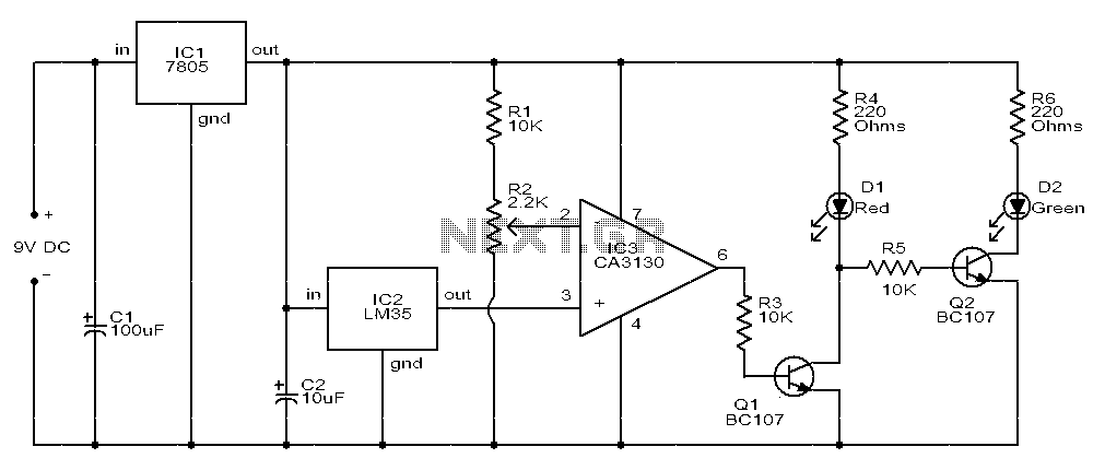
The circuit consists of two light-emitting diodes (D1 and D2) whose operation is controlled by the ambient temperature. A temperature sensor, the LM35, generates an output of 10 mV for each degree of temperature increase. A reference potentiometer, R2,...

An effective domestic alarm system is most effective when it never activates, and the best way to achieve this is to create the illusion that the premises are occupied. Most burglaries are committed by petty thieves who seek simplicity...