
Car Courtesy Light

The power management of the circuit is designed to ensure zero standby power consumption. Relays are utilized for this purpose. The voltage regulator (IC2) remains disconnected from the 12V car supply until the door is opened, activating relay K1, which then powers the voltage regulator and the PIC. The first action of the PIC software is to maintain power by activating relay K4 through port RA4. Once operational, the PIC enters a waiting state until the door is closed, monitored through relay K1 and input port RB0, indicating door closure. When RB0 is grounded, the light turns off, but the PIC immediately reactivates the light using a PWM signal from port RC1 and transistor Q1 at 100% duty cycle. The PIC then waits for 25 seconds (configurable in software) before initiating a dimming sequence (from 100% to 0% over 3 seconds). To prevent relay K1 from buzzing due to PWM voltage, relay K3 is activated prior to dimming. After the light has dimmed to zero, all relays, including K4, are deactivated, powering down the entire device. The 25-second wait time in door mode can be interrupted by grounding RB2 via an external system, which triggers an immediate dimming sequence. Manual activation of the light bulb is possible through switch K2, which powers the PIC similarly but grounds input RB1, switching the software to manual mode. In this mode, the system performs a soft start of the light (dimming from 0% to 100% over 3 seconds), waits for RB1 to return to a high state, then dims the light from 100% to 0% over 3 seconds before shutting off power.
The initial prototype was developed on a Dwengo experimental board, which utilized a PIC18F4550. Two projects were created: one for the PIC18F4550 and the final design for the PIC18F2550. The first project incorporated the Dwengo library for debugging messages on an LCD, while the second did not require this library. The software employs a gamma table (g[] in the source code) to convert percentage values to appropriate duty cycles for the light, ensuring visual consistency with the specified percentage. This table is optimized for LEDs, and adjustments may be necessary for traditional incandescent bulbs.A car courtesy light in a standard car without a board computer is often a very simple thing: you open the door, the interior light is switched on, you close the door, the light is switched off. For convenience, it is very nice to have the light switched on a little longer after the door is closed, for instance to find your keys and start the engi
ne. There are many car courtesy light schematics and ready-to-use devices around on the internet, but this one has a few interesting properties that I could not find on any of them, and that I really wanted. That`s why I decided to build it myself. This circuit is based around the PIC18F2550 microcontroller. This chip is actually a small computer contained in a single chip, including RAM memory, EEPROM, I/O ports, CPU and so on.
When you buy this chip, it comes empty with no program on it. You have to compile the source code and download the resulting machine code into it, using a PC and a small programmer attached to the PC and the chip. To get yourself familiar with this stuff, I suggest you first read this link: Getting started with microcontrollers.
Using a microcontroller to design a car courtesy light extender/dimmer might look like overkill at first glance. A simple 555 timer or a few transistors/resistors/capacitors also might do the job, but considering the characteristics I wanted the device to have, a microcontroller really ended up to be the way to go.
- Absolutely no change needed on the existing wiring, no need to interrupt the wire from door-switch to the light bulb or from +12V to light bulb. In fact, this device use only a one-wire interface to the existing car courtesy light (plus 2 wires for power) - Possibility to immediately switch off the light when an event takes place, for instance when the alarm system is armed or when the car ignition is on As you can see only one wire is connected to the existing wiring, this can be done at any convenient point (e.
g. near the light bulb, near the door sensor or anywhere in between). This connection is referred to as PAD3 in the schematic diagram later on. Optionally, an extra switch (S2, toggle type) can be added for manually controlling the light (PAD4 in the schematic later on). Also an extra signal coming from other systems (e. g. motor on, alarm armed, ) can be used to immediately cut off the light (S3, PAD10 in the schematic). This results in a schematic diagram like this: The tricky thing is that we only have one wire to interface with the existing car courtesy light, and that this one wire is already connected to the light bulb and to the door switch.
We don`t want to change anything on the existing wiring. This is why we use relay K1. It is in fact connected parallel to the light bulb (not considering blocking relay K3 at this moment). This relay will be used to monitor the light bulb while it is lit (car door open) and especially when it is unlit again because the door is closed.
See later on. But first, let`s have a look at power control to the circuit. Since standby power must be zero, relays are used to accomplish this. The voltage regulator (IC2) is normally not connected to the 12V car supply. When the car door is opened, and thus relay K1 is activated, power is provided to the voltage regulator and to the PIC. First thing the PIC software will do, is to insure it will keep itself powered by activating relay K4 (by means of port RA4).
As soon as the PIC is running, it will do nothing but wait until the door is closed, by means of relay K1 and input port RB0. This is referred to DOOR MODE in the software. When RB0 is on ground level, we know the door is closed. The light will go out but immediately the PIC takes over and puts the light back on by means of a PWM signal going out on port RC1 and transistor Q1 (PWM on 100% duty cycle).
Then the PIC will wait for 25 seconds (this can be modified in software) and then start to dim the light bulb using PWM (from 100% to 0% in 3 seconds). Before the dim-period is started, relay K3 is activated to prevent relay K1 buzzing because of the PWM voltage on it`s coil (remember K1 is parallel to the light bulb).
After dimming is finished to zero percent, all work is done and the PIC switches off all relays including K4 thus putting the whole device off. The cycle of waiting 25 seconds while in door mode will be interrupted if RB2 is put on ground level by an external system.
In this case the PIC will start the dim-period immediately. Another way of activating the light bulb is by means of the manual switch, which operates relay K2. This will do about the same (activate the voltage regulator to put the PIC on power), but because this also grounds input RB1 the software will go in another mode. This is referred to as manual mode in the software. This mode will take care of a soft start of the light bulb (dimming from 0% to 100% in 3 seconds), waiting until RB1 goes off ground and then start to dim the light (100% to 0% in 3 seconds) and switch off power.
It was first prototyped on a Dwengo experimental board ( ). Since this board uses a PIC18F4550, I designed two projects: one for PIC18F4550 and one for PIC18F2550 (the final design). The first one also uses the Dwengo library to show some debug messages on the Dwengo LCD, the second one does not need the Dwengo library.
The software uses a gamma table (g[] in the source code) to translate percentage to a correct duty cycle for the light that visually corresponds to that percentage. This table is suitable for LEDs, I don`t know what it will look like on classical light bulbs. It might be needed to change the table in this case. 🔗 External reference
Related Circuits
Children today appear to possess nearly all the items available in toy stores. Therefore, if there is a son or grandson with a collection of toy cars, here is a suggestion for an addition to that collection. For enhancing a...
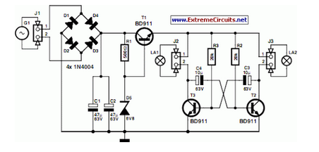
A front wheel with a built-in dynamo was purchased, providing a sine wave output of 30 Vpp at no load. Based on this, a simple power supply was designed using BD911 transistors, which are somewhat oversized for the application,...
I have received countless emails asking for a circuit to tell the user which car won in a pine car (also called Pinewood Derby, Cub Car, Scout Car, etc.) race. This simple circuit takes care of the guesswork, lighting...
The circuit is quite simple and can be utilized as an introductory hardware modification for the NXT platform. A white LED (D1) is powered through a 150-ohm resistor (R1) using the 4.3V power supply from the NXT. The forward...
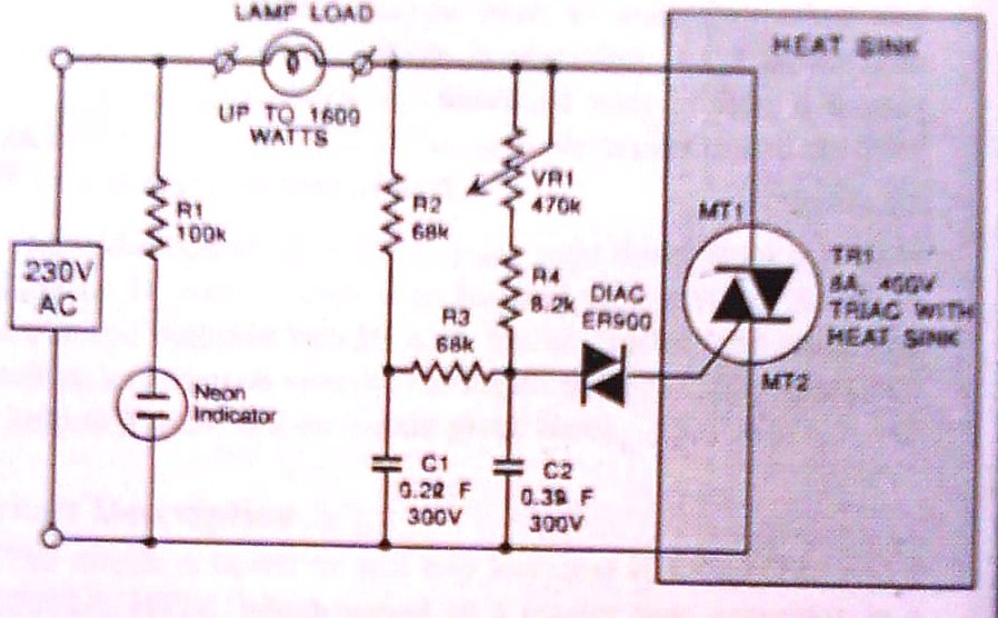
This dimmer is designed to control illumination effectively, with a power handling capacity that exceeds 1600 watts, significantly surpassing the typical 300-watt dimmers. The circuit utilizes a triac rated at 400 PIV and 8 amperes, while component VR1 allows...
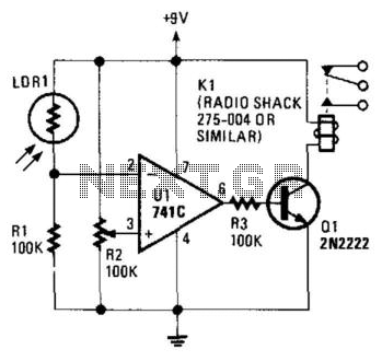
The circuit's threshold is determined by resistor R2. When the intensity of light on the LDR decreases, the resistance of the LDR increases, resulting in a lower voltage at the inverting input of the 741 operational amplifier. The reference...