
Car Antenna Amplifier Circuit

The car antenna amplifier circuit is designed to enhance the reception capabilities of antenna systems, particularly in automotive applications. With a gain of approximately 30 dB, the amplifier significantly boosts weak signals, making it ideal for environments where signal strength is compromised. The input impedance of around 10 kΩ at 30 MHz ensures compatibility with a wide range of antennas, allowing for effective signal transfer without loading the antenna excessively.
To maximize performance and minimize signal loss, the amplifier must be installed directly at the antenna's base. This installation approach mitigates the effects of cable capacitance, which can degrade signal quality, particularly at higher frequencies. The use of high-quality coaxial cables with low loss characteristics further enhances the overall efficiency of the system.
For outdoor applications, the importance of housing the amplifier in a waterproof enclosure cannot be overstated. Environmental factors such as moisture and temperature fluctuations can adversely affect the performance and longevity of electronic components. Therefore, utilizing a robust, weatherproof case will protect the amplifier from the elements, ensuring reliable operation over extended periods.
It is crucial to note that this amplifier is specifically designed for receiver antennas. Attempting to use it for transmitting signals can lead to irreversible damage to the amplifier and potentially the connected equipment. Proper installation and adherence to the intended use of the amplifier will ensure optimal performance and longevity of the system.The total gain of the car antenna amplifier is around 30 dB and the input impedance at 30 Mhz is around 10 K ©. The amplifier must be mounted directly at the base of the antenna to avoid signal losses caused by the capacitive character of the coaxial cable.
This antenna amp must be used for non-mobile recievers. If you intend to install this circu it in you outdoor mounted antenna, make sure that is housed in a water proof case. Use this car antenna amp circuit only for receiver antennas. Transmitting through it will damage the components. 🔗 External reference
Related Circuits
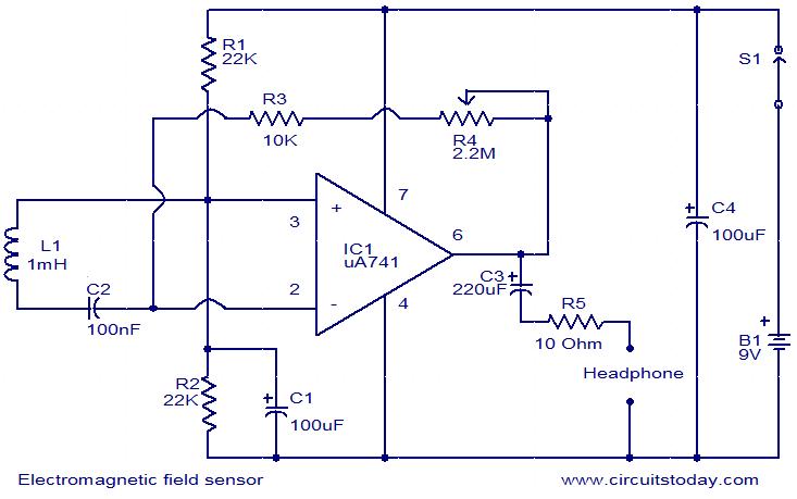
The following circuit illustrates an Electromagnetic Field Sensor Circuit Diagram. This circuit is based on the uA741 integrated circuit. Features: it is used to sense electromagnetic fields. The Electromagnetic Field Sensor Circuit utilizes the uA741 operational amplifier to detect variations...
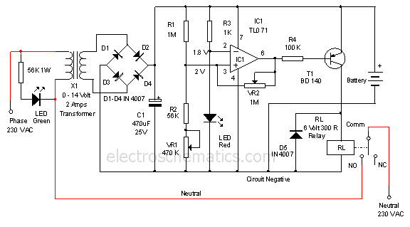
This is a 12-volt lead-acid automatic battery charger that stops the charging process once the battery reaches a full charge. This feature prevents overcharging. The 12-volt lead-acid automatic battery charger is designed to efficiently charge lead-acid batteries while ensuring safety...
This high voltage converter circuit operates from a 30-volt power supply and can output a voltage ranging from 0 to 3 kV in version 1 or from 0 to 10 kV in version 2. The high voltage converter circuit is...
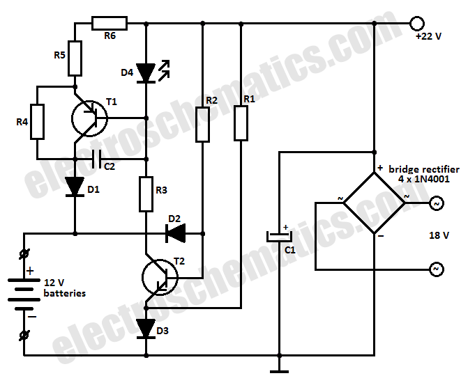
This battery charger circuit is designed to charge one or more batteries with a total nominal voltage of 12 V, which accommodates either ten NiCd batteries or six 2 V lead-acid batteries. The battery charger circuit operates by utilizing a...
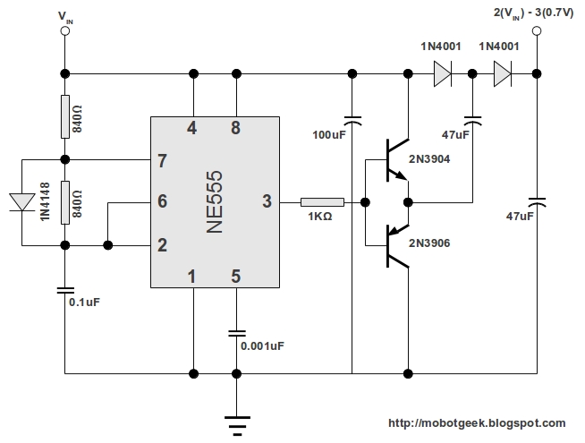
This DC voltage doubler circuit generates a voltage that is double its supply voltage. It is advantageous when a higher voltage level is required from a single lower voltage power supply. Due to the low current consumption in such...
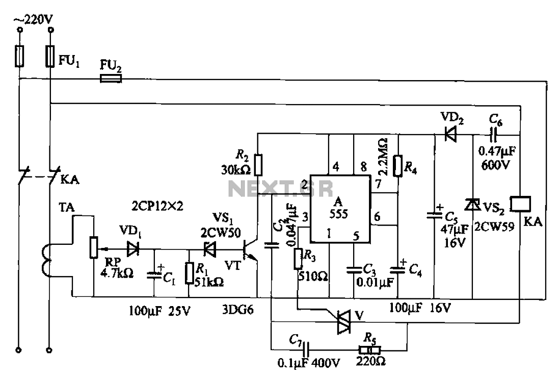
The 555 limit circuit, which is an integrated electrical circuit, is designed to manage large electrical loads. It automatically disconnects power when the load exceeds a predetermined threshold. Once the load is reduced below this threshold, power is restored...