
Night Security LightCircuit

The circuit employs a CMOS IC 4060, which functions as an oscillator and timer. The operational principle relies on the interaction between the LDR and the timing components. The LDR is a critical component that changes its resistance based on ambient light levels. During the day, when light levels are high, the LDR maintains a low resistance, which keeps pin 12 of the IC high, effectively disabling the oscillator function of the IC.
As night falls and light levels drop, the resistance of the LDR increases, resulting in a low signal at pin 12. This change enables the IC to oscillate, generating a square wave output at pin 3. The frequency of oscillation is determined by the values of resistors R1 and R2, and capacitor C4, which are chosen to create a timing delay that results in the output going high approximately 8 hours after the circuit is activated, aligning with the desired time of 2:00 AM.
When pin 3 goes high, it triggers a triac, which is a semiconductor device capable of controlling power to the lamp. The triac allows for the lamp to be turned on at the specified time, providing illumination when it is most needed for security purposes. The manual switch S1 offers a convenient way to override the automatic function, allowing the user to turn the lamp on at any time.
Capacitor C2 is included in the design to suppress any transient signals that might inadvertently trigger the circuit, ensuring reliable operation. This feature is particularly important in environments where electrical noise may be present, as it helps maintain the integrity of the timing function and prevents false activation of the lamp. Overall, this circuit provides an effective solution for enhancing security through timed lighting.This simple circuit switches on a light around 2 hours after midnight, the time at which most of the robberies taking place. This simple circuit is build around a CMOS IC 4060 to obtain the required timing. During day time the LDR has low resistance and keeps the pin 12 of the IC1 high, preventing the IC1 from oscillating.
When it is dark the LDR r esistance becomes high and the pin 12 of IC1 becomes low and the IC starts oscillating, which indicated by the flashing of LED D3. The values of the timing components R1, R2, C4 are so selected that the out put pin3 of IC1 goes high after 8 hours.
That means the high output drives the triac to switch on the lamp around 2`O clock. At morning, the LDR resistance drops and the pin 12 of IC1 goes high and stops the oscillation, making the lamp OFF. The switch S1 can be used to manually ON the lamp. The capacitor C2 prevents false triggering. 🔗 External reference
Related Circuits

The circuit features red lights that chase up and down on the front of the kit, with a pause of about one second between each sequence. Unlike other circuits that continuously pulse a decade counter, this design employs two...
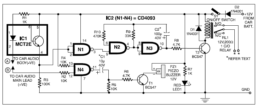
When 12V DC from the car battery is applied to the device (as indicated by LED1) through switch S1, the circuit enters standby mode. The LED inside the optocoupler IC1 illuminates as its cathode terminal is grounded via the...
A general-purpose hobby circuit for a simple light fence security beeper is presented here. This circuit can be utilized as a door alarm, gate alarm, pathway alarm, and more. It can be powered by any 12 Volt DC power...

The TL082 (Or a TL072 also is OK) Creates an Adjustable Sawtooth Generator. (It also has a Square wave Output, but it isn`t used here.) The Left and Right LEDs are connected in series, and if this circuit is used...

This project describes a light effect that is similar to the one of the car in the TV series "Knight Rider." The light effect project emulates the iconic scanning LED light sequence featured in the "Knight Rider" television series. The...

This is a simple update to Mr. Hareendran's PIR Sensor Security Light circuit. It has a shortcoming that limits the relay voltage to approximately 3.3V. While this may function with some 5V relays, it will not function with all. The...