
3V to high Joule Thief inverter circuit

The design of a 3V to 1000V inverter circuit involves several critical components and considerations to ensure proper functionality. The inverter's primary role is to convert low-voltage DC input (in this case, 3V) into high-voltage AC output (up to 1000V). The key elements of the circuit typically include a power source, an oscillator, a transformer, and output circuitry.
1. **Power Source**: The circuit begins with a stable 3V DC power supply. This could be a battery or a regulated power supply. It is essential that the power source can provide sufficient current for the inverter operation.
2. **Oscillator**: An oscillator circuit is required to switch the DC input on and off rapidly, creating a pulsed signal. This can be achieved using transistors, integrated circuits, or dedicated oscillator chips. The frequency of the oscillation will determine the output frequency of the inverter.
3. **Transformer**: The transformer is a critical component in stepping up the voltage from 3V to 1000V. The design of the transformer must consider both the number of turns and the wire gauge used. The turns ratio must be calculated accurately; for instance, to step up from 3V to 1000V, a turns ratio of approximately 1:334 would be required. Using very thin copper wire can lead to excessive resistance, heating, and potential failure of the transformer. Additionally, the core material and thickness are vital for efficient magnetic coupling and minimizing losses.
4. **Output Circuitry**: The output stage may include rectification and filtering components if a DC output is desired. However, if high-voltage AC is the goal, appropriate safety measures must be in place to handle the high voltage safely.
5. **Error Checking**: To troubleshoot the circuit, it is recommended to check all connections for soldering errors, verify component values, and ensure that the oscillator is functioning correctly. Measuring voltages at various points in the circuit can help identify where the failure occurs.
In summary, constructing a 3V to 1000V inverter circuit requires careful attention to component selection and circuit design. The transformer, in particular, must be designed with appropriate wire gauge and core material to ensure efficiency and functionality.I wanted to make 3v to 1000 volts inverter circuit. I already soldered circuit but it doesnt work. I wanted experts to look for errors in my circuit. Also I dont know if I made properly tranformator. It has same number of turns but I ignored wire and core thickness. I used very thin copper wire 🔗 External reference
Related Circuits

The relay power in the linear circuit is derived from a -120 V bias supply, while the transmit keying output from the Kenwood device is +12 V with a maximum current of 10 mA. A critical component of this...
This process can be simplified by utilizing a display kit from PJRC, which includes the appropriate firmware installed on the display, a functioning pushbutton board, and the necessary cables. The PJRC display features a 4-pin connector compatible with the...
An analog meter typically does not exhibit high impedance due to the absence of a buffer circuit within its design. By incorporating active buffering, the input impedance of this circuit can be significantly enhanced. The integration of an active buffer...
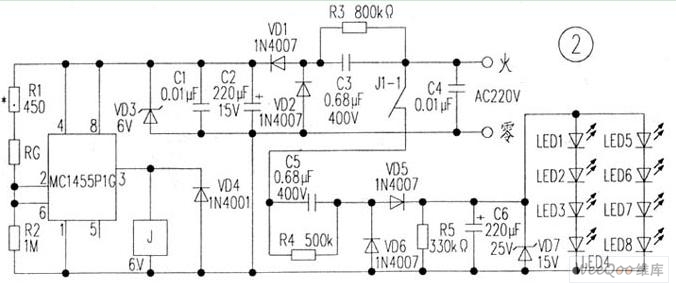
The circuit is depicted in Figure 1, while the electrical schematic diagram is presented in Figure 2. The AC voltage of 220V is reduced by components C3 and R3. The diodes VD1 and VD2 rectify the voltage, and capacitors...
A new user has recently discovered a Laser Alarm System and has decided to explore this project. The Laser Alarm System is a security device that utilizes laser beams to detect unauthorized entry or movement within a designated area. The...
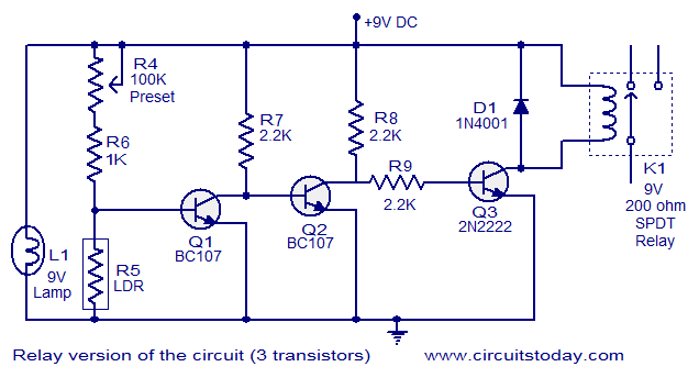
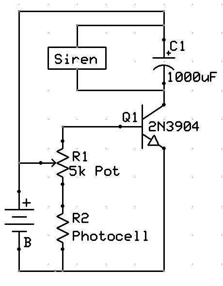
This document describes a simple fire alarm circuit utilizing a Light Dependent Resistor (LDR) and lamp combination for fire detection. The alarm activates by detecting smoke generated during a fire. When smoke is present, the circuit triggers an audible...