
Simple strobe circuit

The described circuit operates as a strobe light generator, utilizing neon and xenon lamps for illumination. Initially, both lamps remain off, presenting high resistance, which allows capacitors C1 and C4 to charge through the voltage doubler configuration formed by diodes D1 and D2. This charging process continues until the voltage across capacitor C3 reaches the ionization potential of neon bulb II, at which point the bulb begins to conduct. The transition from non-conductive to conductive state results in a rapid decrease in resistance, allowing a significant current pulse to flow through the primary winding of transformer T1.
The transformer is designed with a specific turns ratio that steps up the voltage to approximately 400 V on the secondary side, which is essential for the operation of the xenon tube. This tube, unlike the neon bulb, requires an external high-voltage signal (4 kV) to ionize the gas and initiate conduction. Once the xenon tube conducts, it generates a bright flash of light, which is characteristic of strobe lighting applications.
The circuit's operation is cyclical. When fuse F1 conducts, it discharges capacitor C2, resetting the system and allowing the charging process to begin anew. Resistor R2 plays a critical role in controlling the charge rate of capacitor C3, which in turn affects the frequency of the strobe light flashes. By adjusting the resistance, the user can modify the repetition rate of the strobe effect, allowing for customization of the lighting output based on the application's requirements. This design is commonly employed in various lighting applications, including photography, entertainment, and signaling, where precise timing and bright flashes are needed.Initially the neon and xenon lamps are not conducting and act like a very high (almost infinite) resistance. Capacitors Cl and C4 in conjunction with DI and D2 form a voltage doubler circuit, which can charge C2 up to about 300 Vdc after several ac cycles.
Voltage increases as current is supplied through Rl and R2. Neon bulb II will all of a sudden start to conduct when the voltage across C3 reaches II's ionization potential. While conducting, the resistance of the bulb will be relative low. £)ue to this sudden conduction, a pulse of current will pass through the primary of Tl. The turns ratio is such that about 400 V will be developed at the secondary. The xenon tube is similar to the neon bulb in that it produces light when the gas ionizes and conducts. However, it is designed so that an external signal (the 4 kV on the metal ring around the tube) ionizes the gas and initiates the conduction.
When F1 conducts, it discharges C2. At this point, the whole cycle starts over again. The purpose of R2 is to vary the rate at which C3 charges, and hence the repetition rate of the strobe.
Related Circuits
One of the major problems that must be addressed in electronic circuit design is the generation of low voltage DC power supply from mains power to energize the circuit. In electronic circuit design, the conversion of mains AC voltage to...
This surround-sound decoder is based on the "Hafler" principle, first discovered by David Hafler sometime in the early 1970s. The original idea was to connect a pair of speakers as shown in Figure 1, for use as the rear...

This project was a surprise as the BC547 transistor (equivalent to 2N2222) can be used to construct a 500mW linear amplifier that operates across the entire HF band with excellent spectral purity and without the need for neutralization. The...
The circuit was designed to illustrate the use of a tone control circuit, which adjusts audio signals before they are sent to any output device. The tone control circuit serves as an essential component in audio processing systems, allowing for...
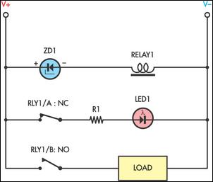
Sensitive low-current relay coils often operate at much lower voltages than their typical ratings. This can be undesirable in some applications, where low supply voltages can result in erratic system behavior. In some instances, this problem could be overcome...

This stereo balance indicator circuit diagram is designed using a few common external components. The schematic circuit is simple to build and provides a visual indication with LEDs for left, right, and center balance. Outputs from each channel are...