
Nixie-clock using neon lamps as logic

The digital clock circuit utilizes a unique approach to driving Nixie tubes by employing neon lamps as the primary logic elements. The choice of neon lamps is critical, as the performance of the circuit hinges on the striking and maintaining voltages that allow for reliable operation in the ring counter configuration. The circuit design includes a series of resistors and capacitors that create a timing mechanism, effectively dividing the 50 Hz mains frequency down to 1 Hz pulses for accurate timekeeping.
The integration of Light Dependent Resistors (LDRs) to drive the Nixie tubes is an innovative solution that enables the display to be activated by the light emitted from the neon lamps. This method requires careful calibration to ensure that the LDRs respond accurately to the neon lamp's illumination while remaining unaffected by ambient light sources. The optical attenuator and filter serve to enhance the reliability of this system by controlling the light levels that reach the LDRs.
The experimentation with blue LEDs for ambient light supplementation highlights an important aspect of the design process, where adjustments are made based on real-world performance. The use of blue LEDs has proven effective in providing the necessary illumination for the ring counters to operate in low-light conditions, showcasing the adaptability of the circuit.
Overall, the circuit's complexity arises from the need to match neon lamp characteristics, manage voltage levels, and ensure stable operation under varying light conditions. The careful selection and testing of components, including the "burn-in" process for the neon lamps, are essential steps in achieving a functional and reliable digital clock. This project exemplifies a blend of vintage technology with modern experimentation, resulting in a unique and personalized electronic timekeeping solution.The above shows my home-built digital clock. It uses Nixie-tubes for readout. In contrast to most other nixie-clocks being built these days, my clock does not use any transistor or IC for driving the tubes. Instead, the driving logic is built from neon lamps, together with resistors, capacitors and silicon diodes.
The project started in 2002, whe n our university library was selling old outdated or otherwise superfluous books, and I very cheaply bought the book "Electronic Counting Circuits" by J. B. Dance, published in 1967, and apparently only ever lent three times by our library, all in 1973. It described how neon lamps can be used as logic elements in a ring counter, exploiting the fact that they need a higher voltage to ignite (the striking voltage) than to stay lit (the maintaining voltage): Unfortunately, if one substitutes the neon bulbs that are available in electronics shops nowadays, the circuit doesn`t work.
Dance used lamps that were specifically manufactured for this type of application, with a large difference between their striking and maintaining voltages. Nowadays, such lamps are (presumably) no longer manufactured; the neon bulbs that are still available in shops are meant as indicator lamps, and have a much smaller difference between their striking and maintaining voltages.
This required changing the circuit`s resistor values, and makes its operation more critical; furthermore, the lamps need to be selected for matching characteristics. Four of these are used, to divide the 50 Hz from the mains power (see here for stability measurements) first by 10 (yielding 5 Hz), then by 5 (yielding 1 Hz, i.
e. , one pulse per second), then further by 10 and 6 to yield one pulse per minute. Note the paper labels still dangling at the cathode wires of the lamps: these are needed to look up the measured properties of each lamp. The nixie tubes are driven through Light Dependent Resistors (LDRs): under the influence of the light from the neon lamp, their resistance lowers, connecting one nixie cathode to the negative power supply.
In order for the LDR not to be influenced too much by ambient light, while still allowing the neon bulb to be visible, an optical attenuator and filter is used between them, consisting of a black cardboard disk with a small hole in it, and two layers of red foil, held together by glue and shrink tube: The ring counters are rather sensitive to ambient light: in complete darkness, they tend not to work. Even though there are always a few bulbs active (if only in the power supply, which is not shown in the photographs), my clock still needs a bit of external ambient light.
I`m experimenting with blue LEDs for providing this extra ambient light. This seems to be quite effective: illuminated by just two blue leds, the clock ran perfectly one night long in otherwise complete darkness: Note though that the blue in this photo is more intense than it looks like in reality: apparently the camera is more sensitive to this shade of blue than the human eye. In contrast to what Dance`s book says, one can`t cascade the ring counters just by connecting them (when using modern-day neon bulbs).
I`m now using an extra neon bulb per counter as an amplifier: it is biased to just under its striking voltage, so a small pulse can strike it. The striking and maintaining voltages of the lamps change quite much during their first hours of operation.
Therefore, it is necessary to first "burn-in" (age) the lamps, before measuring their characteristics. Despite selecting my lamps for matching characteristics, some still acted weird and needed to be replaced.
For example, I had one which somehow didn`t work reliably in the buffer stage; and another one worked reliably in a ring counter when clocked at about 1 Hz, but not when getting a pulse only once per hour. Apparently, fully characterizing the neon lamps requires more quantities than just the striking and mainta
🔗 External reference
Related Circuits
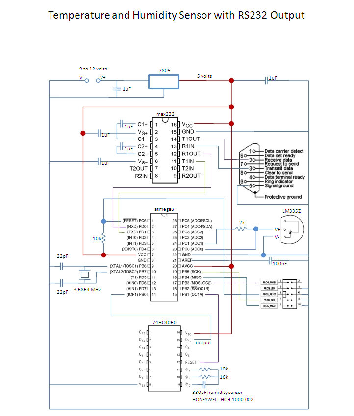
This is an affordable method for measuring temperature and humidity with a computer interface, designed as an entry-level project for high school students on a limited budget. The project involves the integration of a temperature and humidity sensor, such as...
Telephone ringer utilizing 556 dual timers. This circuit generates ringing tones resembling those of a telephone by employing modulated rectangular waves of varying time periods. The telephone ringer circuit employs two 556 dual timer ICs configured to generate modulated rectangular...
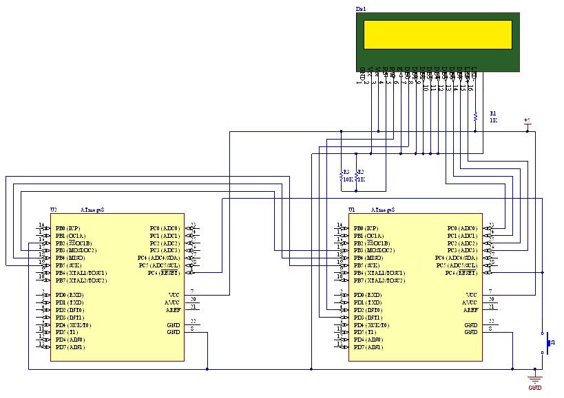
This document outlines the process of transmitting data between a PC and an AVR Atmega8 microcontroller using the USART module. The communication utilizes the COM port of the PC, which is based on the RS232 protocol, and the UART...

This circuit is designed for line detection in a robot project. A proper match between the transmitter and the detector is crucial for optimal operation, particularly when the hole is large. The robot is equipped with a simple system...
Humanity has long grappled with the concept of Time, often seeking ways to interact with it meaningfully. A proposed solution is a knocking platform designed to address these fundamental needs, exemplified by the Knock Block KUI and its associated...
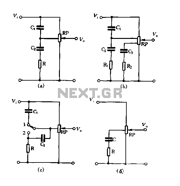
Figure 1.88 illustrates the loudness control circuit utilizing multiple taps on a potentiometer. In Figure (A), the connection is made between the tap and the potentiometer's input, along with the ground. An RC compensation network is employed, where the...