
pic16f877 based controllable digital clock using lcd display codeproteus simulation

The implementation of a controllable digital clock using the PIC16F877 microcontroller involves several key components and steps. The PIC16F877 is an 8-bit microcontroller with a variety of features that make it suitable for timing applications, such as built-in timers, I/O ports, and EEPROM for data storage.
The circuit design begins with the microcontroller connected to a crystal oscillator to provide the necessary clock signal for accurate timing. A common frequency for the oscillator is 4 MHz, which allows the microcontroller to execute instructions efficiently. The oscillator circuit typically includes two capacitors connected to the crystal to stabilize the frequency.
The digital clock will require an interface for user input, which can be achieved using push buttons or a keypad. These inputs will allow users to set the time and switch between display modes (e.g., 12-hour or 24-hour format). The microcontroller's GPIO pins can be configured to read the state of these buttons.
For timekeeping, the microcontroller can utilize its internal timer modules. A timer interrupt can be configured to trigger every second, allowing the program to increment the time count accurately. The time can be stored in the microcontroller's RAM or EEPROM, depending on whether persistent storage is required.
The display of the clock can be implemented using a 7-segment LED display or an LCD module. The microcontroller will control the segments or characters displayed based on the current time value stored in memory. It is also essential to include a driver circuit for the display, especially if using multiple 7-segment displays, to handle the current requirements.
Power supply considerations are crucial for the clock circuit. A stable power source, such as a regulated 5V supply, should be used to ensure consistent operation. Additionally, the design may include a battery backup system to maintain time during power outages.
Lastly, the programming of the PIC16F877 can be accomplished using MPLAB IDE and XC8 compiler. The code will handle input reading, time calculation, display updates, and any additional features such as alarms or timers, providing a comprehensive solution for a controllable digital clock.This PIC16F877 microcontroller tutorial answers the question, "" How to implement a controllable digital clock using PIC16F877 ? "" Using PIC16 simulator (Pr.. 🔗 External reference
Related Circuits
The original FLED-based SE uses a flashing LED to drive a type 1 solar engine (you'll note that it's just like the Zener-based SE, but with a FLED in the starring role). The good news is that all the...
The AD537 is a monolithic voltage-to-frequency (V-F) converter that includes an input amplifier, a precision oscillator system, an accurate internal reference generator, and a high-current output stage. A single external resistor-capacitor (RC) network is sufficient to configure any full-scale...
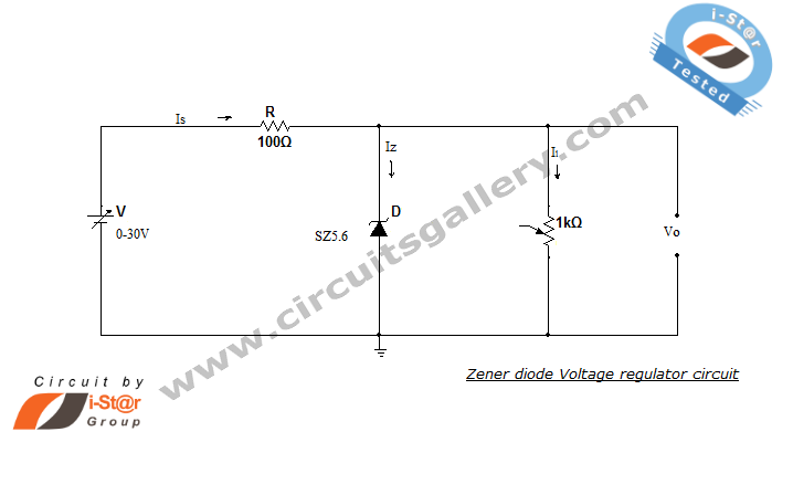
A Zener diode regulator is a fundamental electronic circuit valuable for hobbyists. This circuit provides a regulated output voltage, suitable for biasing other circuit components. The Zener diode operates in the reverse breakdown region, maintaining a nearly constant voltage...
This document describes a PLL FM transmitter utilizing the LMX1601 and either the ATtiny2313 or AT90S2313 microcontrollers. A common feature of previous low-power FM transmitters developed over the years is that their operating frequency is determined by an LC...
The SE555/NE555 timer was first introduced by the Signetics Corporation around 1971. Pin connections and functions are as follows: Pin 1 (Ground) - This pin serves as the ground or common pin, representing the most negative supply potential of...
Normally analogue-to-digital converter (ADC) needs interfacing through a microprocessor to convert analogue data into digital format. This requires hardware and necessary software, resulting in increased complexity and hence the total cost. The circuit of A-to-D converter shown here is...