
Noise in Amp from LED Strip & servo

Additionally, a separate noise issue arises when a servo is connected to the Arduino, creating a constant loud noise in the amplifier output, even when the Arduino and servo are powered by a separate USB supply (with only ground connected). Attempts to separate the audio setup and servo data wires have not mitigated the problem. When the amplifier is removed, the audio stream to the Arduino is clear. Recommendations include adding a resistor between 33k and 100k ohms on the non-inverting input of the op-amp to form a low-pass filter, which can help suppress high-frequency oscillations and radio frequency interference.
The power supply circuit includes two diodes separating the 12V supply to two large capacitors, one feeding the 5V regulator and the other supplying the amplifier. Adjustments have been made, including replacing 100uF capacitors with 470uF and attempting a low-pass filter, which improved the analog input but did not completely eliminate noise from the power lines. Star grounding methods have also been tried without success. Further experimentation with capacitor values across resistors R2 and R4 revealed that increasing R4 from 10k to 150k significantly reduced noise, suggesting that the noise may have originated from R4 connected to a noisy VCC. Additional noise may be introduced through the resistor bridge R1-R2, which centers the signal around VCC/2. Capacitors have been added across VCC and GND connections to mitigate noise. Despite these efforts, some noise remains, particularly during silent moments.
The circuit also lacks RF shielding and ferrite cores, which could help prevent RF interference from affecting the power input. The 10k potentiometer is used to adjust the sensitivity of the microphone.
To enhance the performance and reduce noise in this circuit, several strategies can be employed. First, the layout of the PCB should be reviewed to ensure proper ground planes and minimize loop areas that can pick up interference. Incorporating ferrite beads or cores on power and signal lines can help filter out high-frequency noise. Additionally, using twisted pair wiring for signal connections can reduce electromagnetic interference.
For the power supply, adding larger decoupling capacitors close to the power pins of both the amplifier and the AVR can provide better transient response. Consider using a combination of electrolytic and ceramic capacitors to cover a broader frequency range. Implementing a low-pass filter on the power supply line to the amplifier may also help in filtering out high-frequency noise.
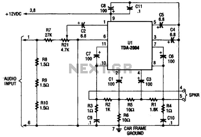
Lastly, shielding the amplifier and sensitive components with conductive enclosures or using RF shielding materials can significantly reduce the susceptibility to external noise sources. These enhancements will contribute to a cleaner audio signal and improved overall circuit stability.TL072 is amplifying an audio signal which is going to speakers & arduino analog input. Amp is powered by a wall wart with 12V 2A output. The same 12V is also regulated to 5V and used to power an AVR. The AVR is being used to PWM, using a power transistor(TIP120), an LED strip taking 1A from the same 12V supply. There 1) Now the rapid switching of current for LED strip is messing up the amplifier output. It`s working fine with LED Strip off but when using PWM, there is a high frequency noise in the amplifier output. I have a 0. 1uF and 10uF caps near power inputs for both AVR and amplifier. This is probably due to insufficient decoupling. Can someone please help me make it better 2) There is another independent source of noise I`m finding which I`m unable to explain.
The audio is going into Arduino which is controlling a servo as well. As soon as the servo is connected, there is a constant loud noise in amplifier output. This remains even after powering the arduino and servo using seperate USB supply(only ground connected). I placed audio setup and servo data wire far apart since they may be interfering due to PWM used for servo, but it wasn`t of any use.
Since in both cases, amplifier is producing noise, I think my amplifier diagram might be at fault. If I remove the amplifier, the audio stream reaches arduino without any noise. Anybody got any ideas how to remove these 2 noises Add a resistor on the non-inverting input of the opamp-something between 33K and 100K. Coupled with the innate input capacitance of the opamp, it should form a low-pass filter. See these in tube amps all the time-it`s called a "grid stopper, " and it helps prevent high frequency oscillation.
and picking up radio stations. It shouldn`t effect the output much-a resistor in series with the input doesn`t change the signal voltage (as a voltage divider would). It may limit current somewhat, but if the input impedance of the non-inverting opamp is high (and it should be very high, possibly 10M or even more) then very little current is required for the opamp`s input to function well.
50K or 60K of in-line resistance here probably wouldn`t even be noticeable. So from your 12 volt supply you have two diodes separating the 12 volt supply to two large capacitors then one goes to the 5 volt regulator and the other to the amp. Will try reversing it. But I think the noise is now at a bearable level. I will put up the whole circuit on the weekend on a breadboard. Thanks for your help! I replaced 100uF caps with 470uF and tried using a low pass filter. Now the analog input is smooth but noise is still going into the power lines. Also tried using star grounding but that didn`t help. I`ll post a diagram soon to help you understand. I tried adding various capacitor values across R2. They did reduce noise but they also reduced audio by about the same amount. That got me thinking and I tried caps across R2 and R4. Turned out if only I increased R4 pot from 10K to 150K, about 80% of the noise went away! Most of the noise was probably due to R4 connected to noisy VCC. The rest of the noise in amp is probably coming through the R1-R2 resistor bridge to center signal about VCC/2.
Any suggestions to eliminate that I tried putting caps across their VCC and GND connections. I have removed most of the noise with the changing R4 to 150K and bigger caps everywhere. I tried out adding the amplifier, arduino, servo and LED strip. The noise was noticeable but only in moments of silence. I`ll try the final complete circuit on the weekend. Thanks for your help. Sounds like you need more shielding. Do you have any kind of RF shielding around the amp Are you using any Ferrite cores to help prevent any RF signals from passing through the power input No, I am not using any shielding or ferrite core. Just components soldered on PCB. The 10K potentiometer is to set the sensitivity of mic and the 🔗 External reference
Related Circuits
This is a design for a low noise microphone preamplifier, which is ideally suited to low impedance (600 Ohm nominal) microphones. One limitation is that it is not balanced, which is not a problem in a home recording environment,...
This design utilizes a well-established circuit topology for the power amplifier, employing a single-rail supply of approximately 60V and capacitor coupling for the speakers. The advantages of this configuration for a guitar amplifier include a straightforward circuit design, even...
Only one channel of this circuit is shown. The other is practically identical. The input to the circuit, taken from the speaker output of a car radio, is divided into two paths. In one path, a high-power divider network...
Each power supply, whether linear or switching, operates in at least two modes: constant voltage (CV) and constant current (CC). The power supply can function in either mode, with the other serving as a protective mode for both the...
Both halves of the circuit are identical. Both inputs have a dc path to ground via the input 47k control which should be a dual log type potentiometer. The balance control is a single 47k linear potentiometer, which at...
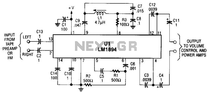
UL is a dedicated integrated circuit (IC) from National Semiconductor that achieves up to 10 dB noise reduction through an adaptive bandwidth scheme and a psychoacoustic masking technique. The UL integrated circuit is designed to enhance audio performance by significantly...