
AMPLIFIER WITH FORCED EQUILIBRIUM ADAPTOR

The operation of a power supply that incorporates both constant voltage and constant current modes involves a careful balance to ensure reliability and performance. The design must include features that facilitate the smooth transition between these modes, which is critical to prevent damage to both the load and the power supply itself. The implementation of a Forced Equilibrium Adapter is one method to achieve this, allowing for more stable operation during mode transitions.
In practical applications, the characteristics of the output filter capacitors play a significant role in determining the performance of the power supply. A small output capacitor can lead to rapid changes in output voltage and current, resulting in potentially damaging transients. Conversely, a larger output capacitor can mitigate these effects by providing a buffer that absorbs transient energy, thus stabilizing the output during mode transitions.
The design of the error amplifier circuit must also account for the time constants associated with the feedback and output filter capacitors. By optimizing these components, the power supply can achieve better control over its output characteristics, reducing the likelihood of uncontrolled transients. Additionally, the selection of current sensing resistors and the configuration of the pass element are crucial to maintaining the desired operational characteristics while ensuring the protective modes function correctly.
Overall, the integration of these concepts into the design of power supplies enhances their reliability and performance, making them suitable for a wide range of applications where stable power delivery is essential.Each power supply, whether linear or switcher, uses at least two operating modes that characterize its operation: constant voltage (CV) and constant current (CC). The power supply can work in either one, while the other is usually a protective mode, both for the load and for the power supply itself.
For example, a constant voltage supply will have a protective CC mode and a constant current supply will have a protective CV mode. The protective or limit mode can be designed to: Be designed to limit both output current and voltage, e. g. , as in a power supply with a foldback-type limit feature, maintaining a quasi-constant dissipated power on the power control element.
The transitions between these two modes, main operating mode and the protective mode, must be automatic and as smooth as possible. Unfortunately, that is not always the case because of the performance of the supply`s error amplifier.
However, this can be corrected by added a Forced Equilibrium Adapter that enables the error amplifier to cope with these operating mode changes. To understand how the Forced Equilibrium Adapter works, we have to first look at the operation of a conventional power supply.
Many variable power supplies have a rectangular voltage-current characteristic as shown in Figure 1(a). However, the rectangular characteristic is ideal, and can be applied only for small variations of the output voltage and current, especially near the "CR" point.
In reality, the transfer characteristic and the transitions between the two modes, CV and CC, could be represented generically by Figure 1(b). During the transitions between modes, both the amplitude of the transients reached by output voltage and current, along with the duration of the transients, depend on: The characteristics illustrated in Figure 1(b) are undesirable because during these transitions the load receives uncontrolled energy which can possibly damage it.
Figure 2 represents a common configuration used for linear type unipolar power supplies. A quick examination of the schematic reveals why the transitions between the two modes produce the transients depicted in Figure 1(b). The output voltage of the controlling error amplifier has a value of few volts, as determined by the configuration of the pass element and the value of the current sensing resistor (Rs), while the output voltage of the other error amplifier, which is out of control, is very close to the +Eaux rail.
Each time control is switched between them, the output voltage of each error amplifier must swing from one value to the other. These swings are delayed by several factors, Because the charge and discharge currents for these capacitors depend on the difference between the new programming value and the final output value, the perturbations introduced by C1 and C2 are "signal" dependent.
Also, there is a delay introduced by the time required to charge or to discharge the overall voltage feedback capacitor C3 and the output filter capacitor C4. Due to these delays, during the transitions between modes, neither error amplifier is effectively in control, being at equilibrium.
Thus, the output voltage and current take on uncontrolled values during this time. The transients described above are significant for power supplies with a small value output capacitor, that produces a short equivalent time constant, compared with the other time constants in the supply. This kind of power supply could be a power amplifier or a regular power supply designed to work in two modes: "fast mode, " with a small value output filter capacitor and "slow mode, " with a large value output filter capacitor.
When working in "slow mode" output transients are "absorbed" by the output filter capacitor, if it is big enough, which spares the load. However, the stress remains on the power supply, because, during transient, the current through the power element reaches an uncontrolled very high value w
🔗 External reference
Related Circuits
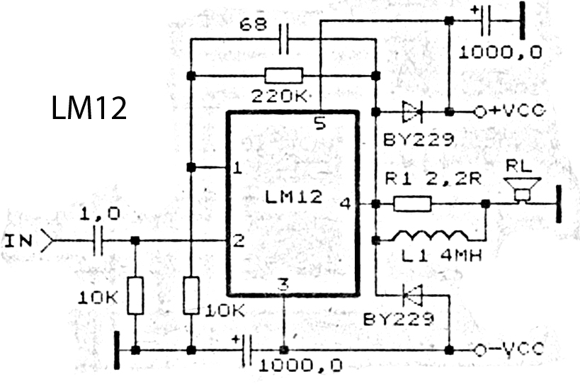
This is an amplifier circuit utilizing the LM12 integrated circuit as the primary amplifier. The amplifier delivers a power output of 150 watts and operates with a load impedance of 4 ohms. It is classified as a high-output power...
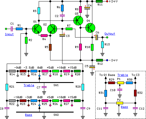
High-quality, discrete component design for input and tone control modules to complement the 60-watt MOSFET audio amplifier with a high-quality preamplifier design. The circuit design focuses on creating a high-fidelity audio preamplifier that enhances the performance of a 60-watt MOSFET...
The amplifier's input stage features a dual-gate GaAs FET, which offers low input capacitance and high transconductance. The first input accepts the signal, while the second input regulates the amplifier's gain. Additionally, there is a third input for series...
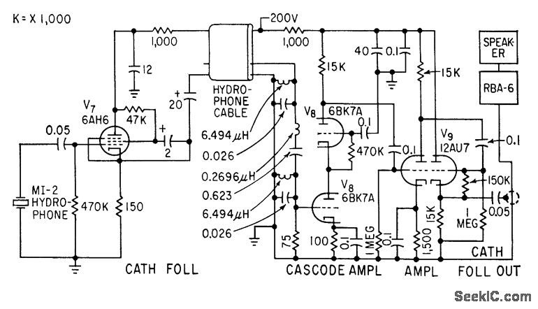
A cathode-follower hydrophone isolation amplifier and high-gain preamplifier are used to feed the Navy RBA-6 low-frequency radio receiver on a trawler. This setup is designed to receive a modulated 21-kc beam that transmits data regarding trawl net depth. The...
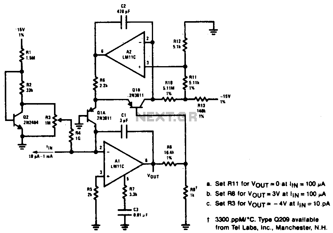
Unusual frequency compensation provides this logarithmic converter with a 100 µs time constant from 1 mA down to 100 µA, increasing from 200 µe to 200 ms from 10 nA to 10 pA. Optional bias current compensation allows for...
The 22-watt amplifier is straightforward to construct and cost-effective. This circuit can serve as a booster in a car audio system, an amplifier for satellite speakers in a surround sound or home theater setup, or as an amplifier for...