
Noisy Regen Receiver

The Noisy Regenerative Receiver Circuit is designed to amplify weak radio frequency signals while also incorporating a regenerative feedback mechanism. This type of circuit is particularly useful in scenarios where signal strength is low, allowing for improved reception of distant radio stations.
The circuit typically consists of a few key components: a transistor or operational amplifier, resistors, capacitors, and an inductor, which acts as part of the tuning element. The regenerative aspect is achieved by feeding a portion of the output signal back to the input, which enhances the gain and sensitivity of the circuit.
In this configuration, the input signal is first filtered through a tuned circuit, composed of the inductor and capacitors, to select the desired frequency. The amplified output is then fed back into the input via a feedback resistor, which is crucial for maintaining stability and preventing oscillations.
The design allows for adjustments to be made to the feedback loop, enabling the user to control the gain and bandwidth of the receiver. This flexibility makes the Noisy Regenerative Receiver Circuit an excellent choice for applications in amateur radio and experimental electronics, where signal clarity and reception range are paramount.
Proper layout and component selection are essential for minimizing noise and maximizing performance. Careful consideration should be given to the placement of components to reduce interference, and the use of shielded cables can further enhance the circuit's effectiveness. Overall, the Noisy Regenerative Receiver Circuit is a valuable tool for enhancing radio signal reception in various applications.The following circuit shows about Noisy Regen Receiver Circuit Diagram. Features: Noisy Regenerative Receiver Circuit, making it easier to .. 🔗 External reference
Related Circuits
This RS-232 type line receiver is designed to drive CMOS logic and incorporates a Schmitt-trigger feedback network that provides approximately 1-V input hysteresis, enhancing noise immunity. A potential issue in an interface connecting two devices, each connected to different...
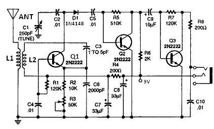
All coils are designed using an inch diameter PVC pipe with 20-gauge insulated hookup wire. L1 requires 6 turns, while L2 requires 14 turns. Additional turns can be added or subtracted from L1 or L2 (or C2 can be...
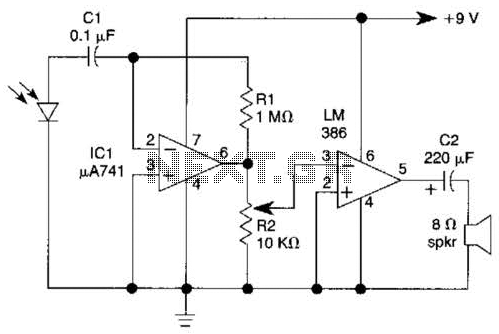
This light-wave receiver comprises a 741 operational amplifier functioning as a preamplifier and an LM386 operational amplifier serving as a power amplifier. The gain control is managed by a potentiometer labeled R2. Various types of detectors can be utilized...
This receiver is designed around the widely used ZN414 integrated circuit (IC) and operates within the AM band, covering frequencies from 550 to 1600 KHz. To utilize the receiver for Longwave frequencies, it is necessary to replace the coil...
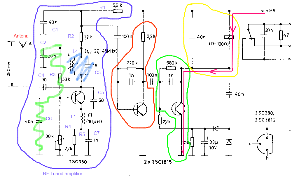
The circuit described is a toy car receiver, which operates similarly to the transmitter but in reverse and with additional filtering. The receiver is tuned to a frequency of 27.145 MHz to capture signals at this frequency. Following the...
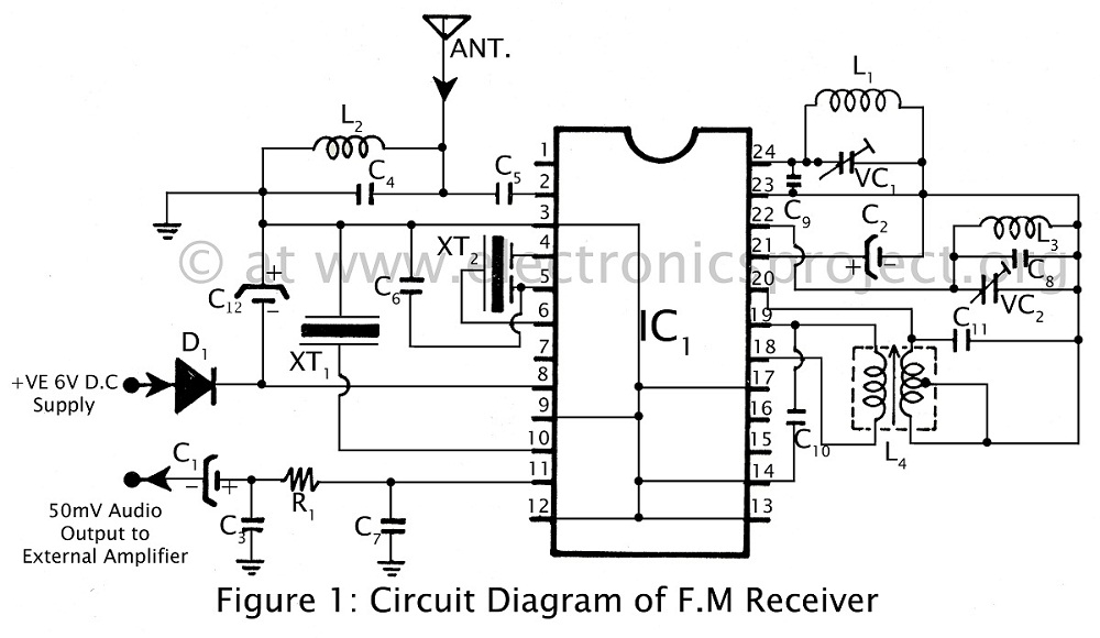
Communication in the FM band is straightforward. This circuit diagram illustrates a powerful FM receiver utilizing a single integrated circuit (IC) that receives frequencies from 88 MHz to 108 MHz within the FM band. The FM receiver circuit described operates...