
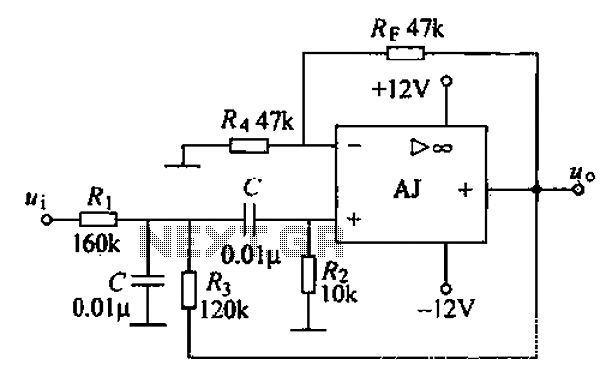
Notch Filter

This circuit is designed to process audio signals, providing flexibility in filtering capabilities. The high-pass filter section is responsible for allowing frequencies above a certain cutoff frequency to pass through while attenuating lower frequencies. This is achieved using capacitive and resistive components configured to create a specific frequency response. The low-pass filter section, conversely, permits frequencies below a designated cutoff frequency to pass, while higher frequencies are reduced. This dual-filter approach allows for the selective manipulation of audio signals, enhancing specific frequency ranges while suppressing others.
The summing amplifier, which follows the filter sections, combines the outputs of the high-pass and low-pass filters. It is configured to provide a gain of approximately 20 times, which amplifies the resulting signal to ensure it is suitable for further processing or output. This amplification stage is crucial for maintaining signal integrity and ensuring that the output is robust enough for subsequent stages in an audio processing chain.
Moreover, the circuit's design allows for additional versatility through the adjustable controls. By modifying the filter parameters, the circuit can be transformed into a band-stop filter, which effectively eliminates a specific frequency range while allowing all others to pass. This is particularly useful in applications where unwanted noise or interference at a certain frequency must be minimized. Alternatively, the circuit can be adjusted to operate as a band-pass filter, allowing only a designated range of frequencies to pass while attenuating both lower and higher frequencies. This feature is essential in various audio applications, such as equalization, noise reduction, and sound shaping.
Overall, the combination of high-pass and low-pass filters, coupled with the summing amplifier and adjustable controls, provides a powerful tool for audio signal processing, allowing users to tailor the sound to their specific needs. The circuit's ability to operate with a supply voltage of +/- 9V DC ensures compatibility with a wide range of audio equipment, making it a versatile choice for both professional and amateur audio applications.At first glance this circuit looks fairly complex, but when broken down, can be divided into high pass and low pass filter sections followed by a summing amplifier with a gain of around 20 times. Supply rail voltage is +/- 9V DC. The controls may also be adjusted for use as a band stop (notch) filter or band pass filter. A variable notch filter with both high and low pass filters. 🔗 External reference
Related Circuits
Digital filters are powerful yet user-friendly, contributing to the popularity of digital signal processing (DSP). For example, a low-pass filter with a cutoff frequency of 1 kHz can be implemented in analog electronics. This method is often utilized for...
An RF force amplifier for FM is essential for amateurs looking to enhance small transmitters, whether they are homemade or commercially available. The presented circuit can deliver 50-60W of RF power with an input control of 15-20W within the...
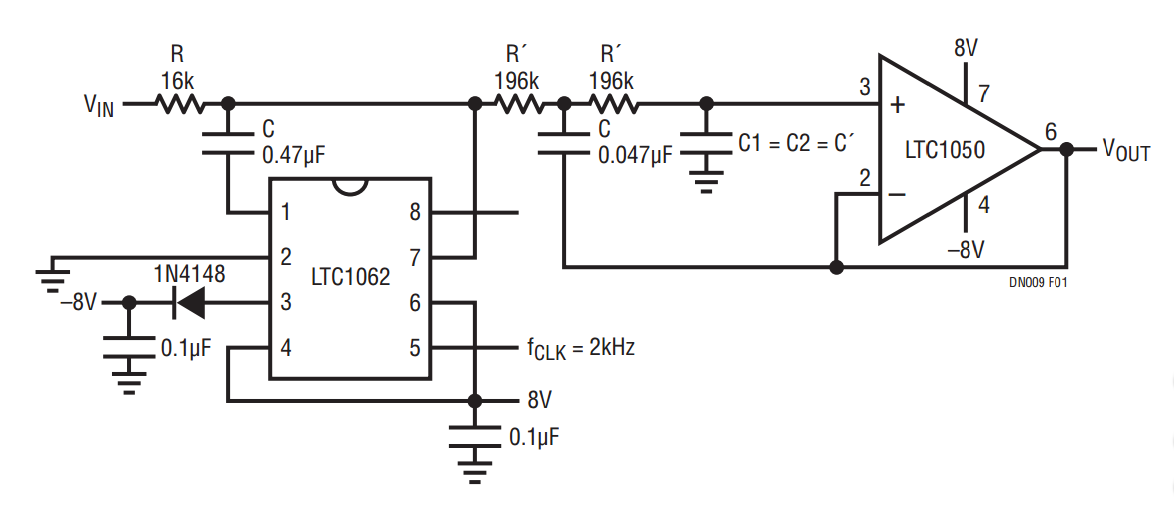
The LTC1050 is configured as unity gain 2nd order low-pass filter which center frequency is (1.2πR´C´) = 1.72 • fCUT-OFF = 17.2Hz and Q = 0.5. Figure 2 shows the amplitude response of the filter, and Figure 3 shows...
A band-pass filter permits only signals within a specified frequency range to pass through, while attenuating or suppressing those outside this range. This is characterized by a lower frequency limit and an upper frequency limit. A typical implementation is...
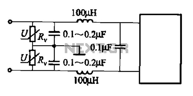
A common low-pass filter circuit is illustrated. Figures (a) to (c) demonstrate its ability to suppress high-frequency interference, while Figure (b) shows a varistor that can absorb lightning surge voltage. Figure (d) indicates the circuit's capability to suppress low...
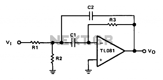
The operational amplifier (op amp) is configured in inverting mode. Resistor R3 connects the output to the inverting input, establishing the gain and the current through the frequency-determining capacitor, C1. Capacitor C2 provides feedback from the output to the...