
Voltage-controlled voltage source second order band-pass filter circuit

The band-pass filter is a critical component in various electronic applications, particularly in communications and signal processing. It is designed to allow frequencies within a certain range to pass while attenuating frequencies outside this range. The design typically employs a second-order configuration, which provides a steeper roll-off at the cutoff frequencies compared to first-order filters, thereby improving selectivity.
In the proposed voltage-controlled voltage source (VCVS) configuration, the filter's bandwidth can be dynamically adjusted. This is achieved by varying the control voltage applied to the filter circuit, which alters the reactive components (such as capacitors and inductors) in the filter design. This feature is particularly useful in applications where the signal environment may change, allowing the filter to adapt without needing physical modifications.
The use of the AJ dual op-amp vA747 in this circuit provides several advantages. The operational amplifier's high gain and low noise characteristics contribute to the overall performance of the filter. The dual configuration allows for the implementation of multiple stages within a compact layout, enhancing the circuit's efficiency and reducing component count.
The design of the band-pass filter involves selecting appropriate resistor and capacitor values to set the desired center frequency and bandwidth. The center frequency, defined as the frequency at which the filter's response is maximized, can be calculated using the formula:
\[ f_c = \frac{1}{2\pi\sqrt{LC}} \]
where \( L \) is the inductance and \( C \) is the capacitance in the circuit. The quality factor, \( Q \), which determines the selectivity of the filter, can also be adjusted through component values.
In practical applications, this band-pass filter can be utilized in RF communication systems, audio processing, and any system where signal integrity is paramount. By maintaining a sharp cutoff and allowing for dynamic bandwidth adjustment, the filter can effectively isolate desired signals from unwanted noise, enhancing overall system performance. Band pass filter allows only signals within a certain frequency range pass through rather than the pass band lower frequency than the upper limit of the low and high frequency signals are to be attenuated or suppressed. A typical voltage-controlled voltage source second order band-pass filter as shown in FIG. The advantage of this circuit is to change the ratio of wind RF bandwidth can be changed without affecting the center frequency. FIG integrated operational amplifier AJ dual op amp vA747.
Related Circuits

This design circuit for audio amplifiers with DC coupling to the load is not commonly used today, despite its clear advantages. One advantage is the elimination of the need for a second (symmetric) power supply, and another is the...
The objective is to enhance information transmission through the distribution of articles. Please contact us via email at [email protected] within 15 days if there are any issues related to article content, copyright, or other concerns. Prompt deletion will occur...
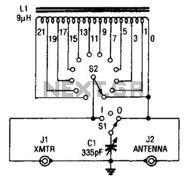
This antenna tuner is designed for low-power transmitters or shortwave receivers with a maximum power output of 5 watts. The switch S2 is used to select the inductance, while S1 connects a 365-pF capacitor either to the transmitter or...
The tone generator was a straightforward project developed as a test unit for a customer design job. It utilizes two analog switches controlled by microprocessor code: one switch manages the signal directed to the operational amplifier that drives the...
A small circuit that can find a lot of applications for measuring time. It has the capability to inform with a sound signal from the BZ1. At the same time, there exists the possibility to drive an external circuit...
An LED flasher circuit can be constructed using a 555 integrated circuit (IC). The use of the 555 IC allows for greater flexibility in adjusting the flashing rate of the LED. This LED flasher circuit is similar to other...