
Notch filter uses an operational amplifier

The notch filter is designed to attenuate a specific frequency while allowing others to pass through. In audio applications, this is particularly useful for eliminating unwanted frequencies, such as hum or noise, without affecting the overall audio quality. The filter's design typically employs a combination of resistors, capacitors, and operational amplifiers to achieve the desired frequency response.
To achieve the specified tuning range of 300 to 1500 Hz, the filter's components must be carefully selected. The central frequency of the notch can be adjusted by varying the resistance and capacitance in the circuit. This can be accomplished through the use of variable resistors (potentiometers) or by utilizing capacitors with different values. The frequency response can be analyzed using a Bode plot to ensure that the filter effectively attenuates the target frequency while maintaining a flat response in the passband.
In practical applications, the notch filter can be implemented in various configurations, including passive and active designs. Passive notch filters typically consist of passive components and are simpler but may have limitations in terms of gain and bandwidth. Active notch filters, on the other hand, use operational amplifiers to provide gain and can offer better performance in terms of selectivity and stability.
Overall, the design and implementation of a notch filter for tunable band-reject applications require careful consideration of component values and circuit topology to ensure optimal performance in the specified audio frequency range.This notch filter is useful for tunable band-reject applications in the audio range. The values shown will give a tuning range of about 300-1500 Hz.
Related Circuits
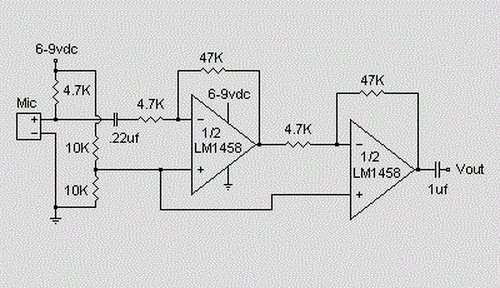
This is a simple preamplifier circuit designed for an electret condenser microphone, utilizing an LM1458 dual op-amp integrated circuit (IC). The circuit amplifies the audio signal from the condenser microphone, allowing it to be used as an input for...
The ICs LM4651 and LM4652 are types of MOSFET integrated circuits and power amplifiers that include high-efficiency amplifiers, making them suitable for self-powered speakers, subwoofers, and high-quality car audio systems. The LM4651 is a fully integrated conventional pulse width...
What value of potentiometer should be used for the volume control of this audio amplifier circuit, and where should it be connected? Thank you. In audio amplifier circuits, the choice of potentiometer value for volume control is crucial for achieving...
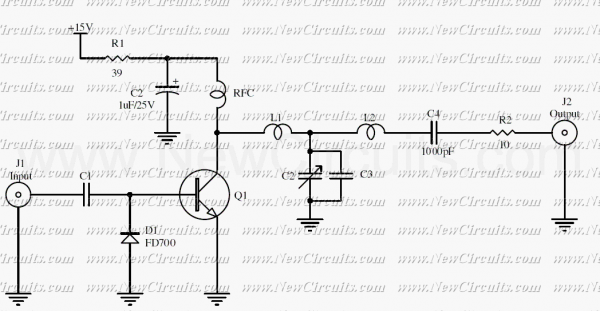
The RF circuit is a C-Class power amplifier. It is used in the last stage of transmitters. Its maximum power output is about 1 Watt. The circuit can be used in 3 frequency ranges: 30-100-200 MHz. More: The P-Out...
The RF amplifier is similar to the one used in the 2.5 MHz amplifier. At a frequency of 10 MHz, the capacitances of a power MOSFET become significant. Noiseless feedback using transformers is no longer straightforward. Intermodulation and overtones...
Utilize a V2-400 subwoofer amplifier for the center channel, and incorporate a separate Digital Converter specifically for the added subwoofer amplifier to initiate a V5.1 system. Place all preamplifiers within the subwoofer enclosure and design a digital control box...