
Microphone Condenser Pre Amplifier Circuit

The described preamplifier circuit serves as an essential interface for electret condenser microphones, which are commonly used in various audio applications due to their compact size and sensitivity. The LM1458 dual op-amp IC is a versatile component that provides two independent, high-gain, frequency-compensated amplifiers. In this configuration, one op-amp is utilized for amplifying the microphone signal, while the second can be used for additional processing or buffering if needed.
The circuit design begins with the electret condenser microphone, which converts sound waves into an electrical signal. The output from the microphone is typically very low, necessitating amplification to bring it to a usable level. The LM1458 is powered by a supply voltage ranging from 6 to 9 volts, which is sufficient to ensure optimal performance while preventing distortion.
The gain of the preamplifier can be adjusted through the 47kΩ resistor. By increasing this resistor's value, the gain of the circuit can be enhanced, allowing for better sensitivity and performance with various microphone types. The 10kΩ potentiometer allows for further customization of the output level, providing flexibility depending on the requirements of the subsequent audio processing equipment.
For optimal performance, it is advisable to house the microphone and associated circuitry in a small round enclosure. This helps to reduce unwanted noise and interference while providing a neat and compact design. Proper grounding and shielding techniques should also be employed to minimize hum and ensure a clean audio signal output. Overall, this preamplifier circuit is a practical solution for interfacing electret condenser microphones with devices that require higher signal levels.This is a simple preamplifier circuit for electret condenser microphone. using a LM1458 dual op amp IC. The circuit takes the audio signal rom the condenser microphone and amplifier it, so you can use the microphone as the input to some device which wouldn`t normally accept microphone level signals. The circuit requires a 6-9 volt supply. Output of the microphone amplifier can be made variable by connecting a 10k © potentiometer. Circuit`s gain can be increased by men perbesar the value of 47K, depending on the input sensitivity of the main amplifier system. The microphone should be housed in a small round enclosure. 🔗 External reference
Related Circuits
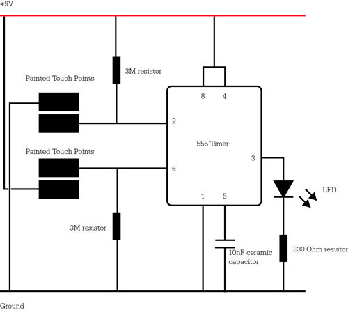
The following circuit illustrates a Solar Tracker Circuit Diagram. This circuit is based on the LM339 integrated circuit. Features include a 10nF ceramic capacitor (103z) and a 1MΩ resistor. The Solar Tracker Circuit utilizes the LM339 quad comparator IC to...

This circuit produces a soft turn-on for halogen lamp filaments upon powering up. The MOSFET used is a BUZ10, which has a resistance of 0.2 ohms. Resistors R1, R2, and capacitor C1 set the turn-on rate, while diode D1...
This radio modem is widely used for amateur radio packet applications. It is powered by the data and control lines, eliminating the need for additional power sources. The radio modem operates by facilitating packet data communication over amateur radio frequencies....
Ensure that connections are verified against the circuit diagram and schematic provided below. This can be utilized while following the tutorial video. The circuit diagram serves as a crucial reference for accurately assembling electronic components in a project. It illustrates...
Two identical integrated circuits, U1 and U2, known as "hex inverters" are used for the theremin's primary functions. They are CMOS (Complimentary Symmetry Metal Oxide Semiconductor) devices, typically used in digital circuits to perform a logic function called "inversion."...
The power supply has been simplified. Power transformers and rectifiers have been omitted, and some components from the MOSFET voltage regulator circuits have been removed, including 1N5242 zener diodes between the source and gate and 10k resistors in series...