
Null detector

The null detector circuit is designed to provide a visual indication of the relationship between a test resistor (R*) and a reference resistor (Rref) using an LED as an output indicator. The core component of this circuit is the operational amplifier (op-amp), specifically the 741 model, which is configured in a differential mode to compare the voltages across the two resistors.
When the resistance of R* matches Rref, the op-amp output stabilizes at approximately half of the supply voltage, which is typically around 4 volts in a dual-supply configuration. This mid-range voltage causes LED A to turn on, providing a clear visual signal that the two resistances are equal.
In scenarios where R* is either less than or greater than Rref, the op-amp output will either increase or decrease, leading to the activation of one of two transistors in the circuit. The transistor that is turned off will stop conducting, while the other transistor will allow current to flow through either output B or C, depending on the direction of the voltage difference. This configuration ensures that the circuit can indicate both conditions of being below or above the reference resistance.
The null detector circuit can be further enhanced by incorporating additional features such as hysteresis to prevent false triggering or adding a more sensitive LED output to indicate small deviations from the null point. Additionally, the circuit could be designed to include adjustable reference resistance, allowing for greater versatility in testing various resistor values. Overall, this simple yet effective design serves as a practical tool in electronic testing and measurement applications.Null detector uses simple LED readout to indicate if test resistor R* is below, equal to, or greater than test resistance Rref. IfR* = Rref, the 741 output sits at midpoint value of 4 volts and LED A lights Otherwise, the output of the 741 turns off one transistor and diverts current from the other transistor through B or C, depending on the polarity of the input voltage difference. Null-detector response is illustrated.
Related Circuits
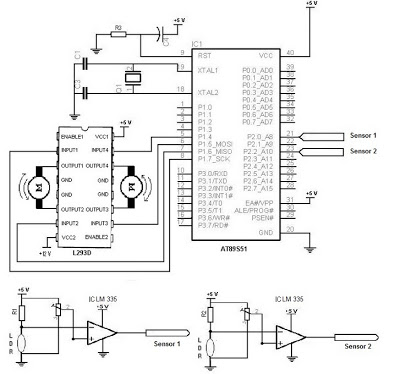
The electronic schematic of the Light Detector Robot can be divided into three main components: the sensor, the microcontroller, and the DC motor driver. The light sensor utilized in this design is a Light Dependent Resistor (LDR), which alters...
The schematic presented is a circuit designed for monitoring plant watering, also known as a dry soil detector. Indoor plants, whether in homes or offices, require more attention compared to outdoor plants. Due to busy schedules, it is common...

The detector is a bit more complex. It amplifies a microphone and sends the resulting signal to an NE567 tone decoder. The amplifier is half of a 1458 opamp. The two 120K resistors attached to pin 3 keep the...
The circuit consists of two oscillators, both working at about 465 kHz. One uses an if transformer and the other uses an inductor (the search coil LI). The oscillators are coupled by a capacitor (10 pF). A beat note...
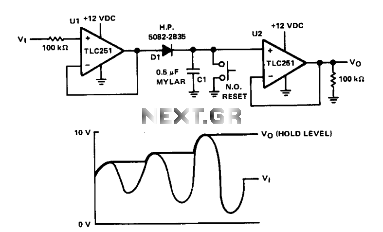
The circuit is designed to capture and hold the peak input voltage on capacitor C1, allowing the output voltage V0 to be read at the output of operational amplifier U2. Operational amplifiers U1 and U2 are configured as voltage...
The site features several low-power transmitters, but until now, there has been no receiver. This circuit can be utilized to scan an area or room, indicating whether a surveillance device is active. The challenge in creating an effective detector...