
OCL AC negative feedback amplifier analysis

The AC negative feedback circuit leverages the principles of feedback to stabilize and control the gain of an amplifier. The configuration typically includes a combination of resistors and capacitors, where resistors R6 and R7 play crucial roles in determining the gain and sensitivity of the circuit. The feedback mechanism provided by these components allows for improved linearity and reduced distortion in the output signal.
The formula for gain, K_v (1 + R7)/R6, indicates that the gain can be adjusted by varying the resistance of R7. This flexibility is essential in applications where precise control over amplification is required. By incorporating an adjustable resistor for R7, designers can fine-tune the gain to meet specific performance criteria.
The circuit's sensitivity S is a critical parameter that reflects how efficiently the amplifier responds to input signals relative to its output power capabilities. The relationship between the rated output power P and the circuit sensitivity can be expressed through the voltage levels at the output. Understanding this relationship allows engineers to design systems that can effectively handle varying input conditions while maintaining desired output characteristics.
Maintaining the symmetry of the differential amplifier circuit is vital for ensuring consistent performance. The adjustment of R2 in tandem with R7 is a design consideration that helps achieve this symmetry. By ensuring that R2 equals R7, the circuit can maintain balanced conditions, which is fundamental for minimizing common-mode signals and enhancing the overall stability of the amplifier.
In summary, the AC negative feedback circuit is a sophisticated design that utilizes resistive and capacitive elements to create a stable and adjustable amplification system. The careful selection and adjustment of components such as R6, R7, and R2 are essential for achieving optimal performance in various electronic applications.AC negative feedback circuit is composed of R R and islands (Figure 1-30), since the C3 AC can be regarded as a short circuit, the actual results shown in Figure 1-32 o It is a n AC voltage series negative feedback o determines the gain of the negative feedback amplifier circuit (amplification circuit) o it is calculated as: K v (1 + R7)/R6. the gain amplifier circuit also determines the sensitivity of the circuit means that the circuit sensitivity S: reached yet rated input voltage when the output power is really needed, its size is determined by the voltage amplification circuit of calculating its decision.
law: Let rated output power P, then the voltage at the rated output power vo /W scale L, circuit sensitivity s V O/Ku. in general, the size of the gain adjustment circuit by changing the resistance R7 to carry out, so some circuit will be designed as an adjustable resistor R7.
it is worth noting that after changing the resistance of R7, R2 resistance should follow the change, so that R2 R7, which can keep the level of the differential amplifier circuit is symmetrical, to improve the stability of the circuit.
Related Circuits
This preamplifier offers a loading ratio of better than -70 dB (referenced to a 10-ohm reluctance phono cartridge) and accepts millivolt input at 1 kHz. It has a dynamic range of approximately 35 dB of gain at 1 kHz...
This delay can be used in power amplifiers to prevent the fuses from failing when the amplifier is turned on. The circuit is very simple with a relay that is turned on when C2 and C3 are charged. If...
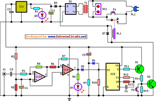
This circuit deactivates an amplifier or any connected device when a low-level audio signal is absent at its input for at least 15 minutes. Activating switch P1 powers the device, enabling operation of any appliance connected to SK1. The...
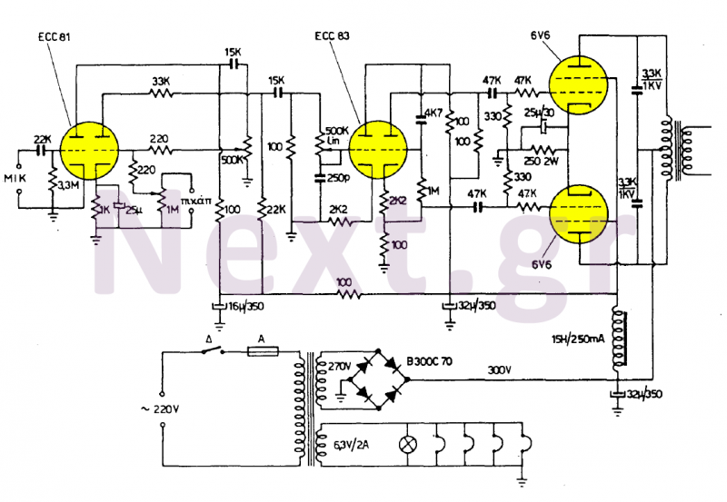
These two amplifiers are of high quality, simple, and economical to manufacture. They feature two inputs: one for a 4mV (500KΩ) sensitivity microphone and another for any 200mV (1MΩ) sound source, with the first input designated for speech and...
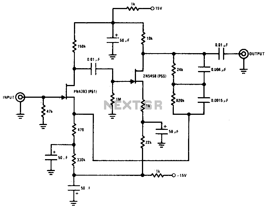
The lower FET operates in common source mode, while the upper FET operates in common gate mode, achieving full high-frequency gain. The bottom FET is tunable, allowing for peak adjustment for a particular station. Coil details follow: The described circuit...
A compact power amplifier that delivers high-quality sound. It incorporates a NE5534 operational amplifier, known for its excellent performance, capable of handling low loads, providing high speed, and exhibiting low distortion. Additionally, it features two V-MOSFET transistors at the...