
Octave Equalizer Circuit

The octave equalizer circuit is designed to enhance audio signals by allowing specific frequency bands to be adjusted independently. Each section of the equalizer corresponds to a specific octave band, enabling precise control over the audio spectrum. The operational amplifier used in this design, the OP-08, exhibits low input bias current, which is advantageous for maintaining signal integrity and minimizing distortion.
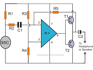
The capacitors C1 and C2 are crucial for determining the center frequencies of each octave band. By selecting appropriate values for these capacitors, the circuit can be tuned to target specific frequencies, thus allowing the user to boost or cut audio levels as desired. The resistor R2 acts as a variable element in the circuit, enabling the adjustment of gain and attenuation. When R2 is positioned to allow maximum resistance, the circuit can achieve a 12 dB cut, while a lower resistance setting will provide a 12 dB boost.
The ability to scale resistors by a factor of 10 is particularly beneficial for low-frequency applications. This scaling reduces the necessary capacitance values, which can help in minimizing the physical size of the components and improving the overall performance of the circuit. Additionally, the low supply current requirement of 6 mA for 10 sections makes this design efficient, allowing it to be integrated into various audio systems without significant power consumption.
Overall, this octave equalizer circuit provides a versatile solution for audio signal processing, enabling users to tailor sound characteristics to their preferences while maintaining high fidelity and low power consumption. This circuit is one section of an octave equalizer used in audio systems. The table shows the values of CI and C2 that are needed to achieve the given center frequencies. This circuit is capable of 12 dB boost or cut, as determined by the position of R2. Because of the low input bias current of the OP-08, the resistors could be scaled up by a factor of 10, and thereby reduce the values of CI and C2 at the low-frequency end. In addition, 10 sections will only draw a combined supply current of 6 mA maximum.
Related Circuits
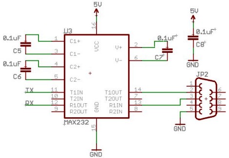
Select a free schematic drawing software that resembles the two mentioned. There have been discussions regarding circuit drawing software. Fritzing is favored, although it lacks certain components, such as the RS232 component. There is a request for feedback on...
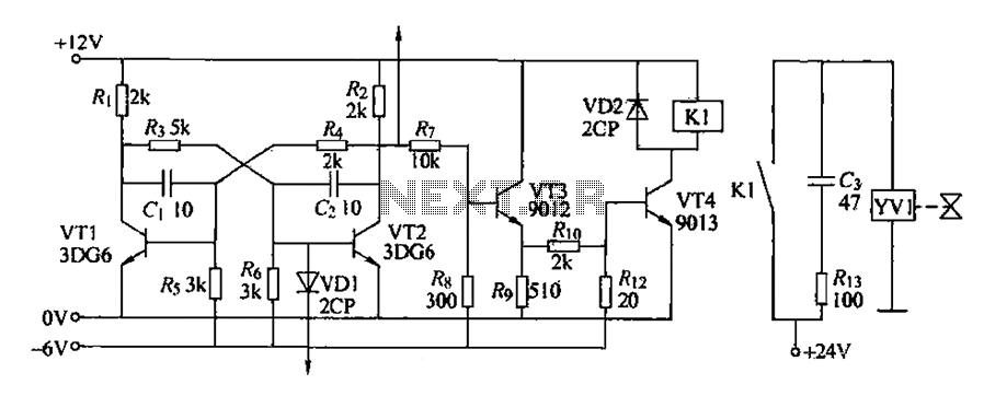
The circuit for detecting bad book binding is not illustrated. The solenoid valve is used to control the head of the YV1 mechanism for handling bad books. Under constant conditions, there is no positive signal indicating a bad book....

Another application of the frequency-to-voltage converter (FVC) is the tone/frequency decoder. This circuit is designed to identify the frequency band of an oscillating signal. It is utilized in various applications, such as determining the frequency band in signals and...
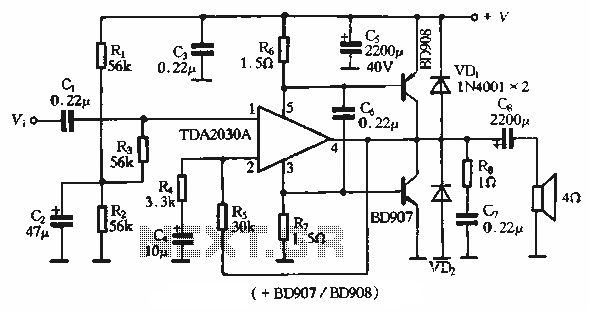
The rDA2030A TDA2030 is an enhanced version of the original product, with a maximum working voltage increased to 18V and a maximum output power of 18W. Additionally, harmonic distortion has been significantly reduced. The application circuit is illustrated. The rDA2030A...
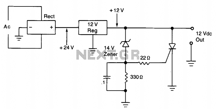
The silicon controlled rectifier (SCR) is designed to handle at least the current provided by the power supply. It is connected in parallel across the 12 V DC output lines but remains inactive until a voltage is applied to...
This document discusses the creation of an electronic spy bug circuit using two methods: one involving a wired connection from the transmitter to the receiver, and the other being a completely wireless setup capable of eavesdropping on conversations up...