
Bad book is not binding circuit

The described circuit functions as a detection and control mechanism for identifying and managing defective books during a binding process. The core of this system relies on a flip-flop configuration, which toggles its state based on the input signals received from the detection of bad letters. The left transistor (VTI) and right transistor (VT2) serve as a bistable multivibrator, where the state of the output is determined by the presence of a faulty book.
In the inactive state, VT2 is on, allowing current to flow through it, resulting in a collector voltage of 0V. When a bad book is detected, the flip-flop is triggered, causing VT1 to turn on. This action turns off VT2, leading to a collector voltage increase to +9.5V. This voltage change is critical as it serves as the input to the next stage of the circuit.
Transistor F3 acts as a current amplifier, enhancing the signal generated by the flip-flop. When the output from the flip-flop switches to +9.5V, F3 is activated, which in turn controls VT4. The conduction of VT4 is significant as it allows current to flow through relay K1. Once K1 is energized, it activates the electromagnetic mechanism YV1, which is responsible for adjusting the binding head. This mechanism ensures that any book identified as defective is not subjected to the binding process, thereby maintaining quality control within the operation.
The circuit can be further enhanced by incorporating additional features such as indicators for system status, feedback loops for error correction, or integration with a microcontroller for more sophisticated processing and control. Such enhancements would provide a more robust solution for managing book binding operations, ensuring that only properly formatted books proceed through the binding stages. Bad book binding circuit not shown, do the solenoid valve to control the head of the YV1 bad book is not set, no positive signal of bad books under constant conditions, the fli p-flop of the left tube VTI off right tube VT2 turns on, then the collector voltage VT2 is ov. If bad letter into the trigger number, this flip-flop flip, the state turned to the left tube VT1, VT2 off the right tube, the collector voltage vri to +9. 5V. This signal is current-amplified by f3 control VT4 conduction, the relay Kl pull, electromagnetic Yan YV1 action, the head of the control is not a bad book to the binding.
Related Circuits
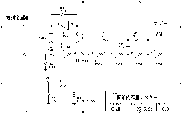
Continuity tester to check continuity in the circuit (Insakittochekka) is. The continuity check over the circuit board wiring that can be checked at a lower voltage semiconductors do not conduct contained in the circuit, you can just check the...

Any NPN transistor can be used. The author used a 2N3904, but a 2N2222A should work just as well. A good, low noise transistor would be even better. Some radios only have three connections to their ferrite bar antenna:...
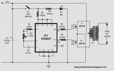
It is recommended to have a fuse in the power line and to always have a load connected while power is being applied. The fuse should be rated at 10 amps per 100 watts of output. The power leads...

The telephone line tester comprises a meter used to measure line voltage in both the on-hook and off-hook states, three resistors (including one variable resistor), a pushbutton switch, and a modular telephone connector. When the circuit is connected to...
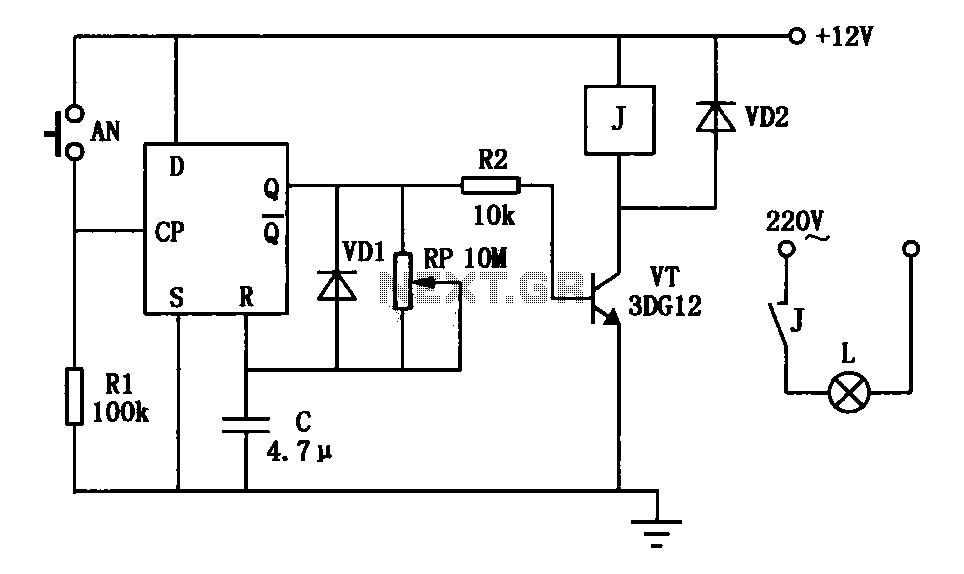
An exposure timer circuit is illustrated using D flip-flops, allowing for timing adjustments between 1 to 30 seconds. The D flip-flop circuit is connected to a one-shot timer. When exposure is required, pressing button AN generates a pulse that...

This is a simple smoke alarm circuit using a timer IC, the NE555. The circuit operates by illuminating a Light Dependent Resistor (LDR) with a lamp. When smoke obscures the light from the lamp, the resistance of the LDR...