
off infrared remote control schematic

The 74HC74 is a dual D-type flip-flop that operates with a supply voltage range of 2V to 6V, making it versatile for various digital logic applications. Pins 7 and 14 are critical as they correspond to the ground and Vcc (supply voltage) connections, respectively. The flip-flop can be used in applications such as data storage, frequency division, and pulse generation. The output state of the flip-flops changes on the rising edge of the clock input, allowing for synchronous operation.
The MOC3041 is an optocoupler designed for AC applications, featuring a phototransistor output that is isolated from the input side. This component is beneficial for interfacing between high-voltage AC circuits and low-voltage control circuits, providing safety and signal integrity. The internal LED of the MOC3041 is activated by the AC input, which in turn triggers the phototransistor to conduct, allowing for signal transfer without direct electrical connection.
The specified zener diode, 1N5352, is a 15V, 4W device that serves to regulate voltage in the circuit. It maintains a stable output voltage by allowing current to flow in the reverse direction when the voltage exceeds its breakdown voltage. This characteristic makes it suitable for protecting sensitive components from voltage spikes and ensuring stable operation within the specified voltage range.
In conclusion, the combination of the 74HC74 flip-flop, MOC3041 optocoupler, and the 1N5352 zener diode provides a robust solution for digital logic applications, AC signal isolation, and voltage regulation, respectively. Each component plays a crucial role in ensuring the reliability and functionality of the overall circuit design.As per the note on the schematic IC-2 is a 74HC74 TTL chip, look up the data sheet and it will show you what pins 7 and 14 are. The note for IC-3 is down lower its an AC optocoupler part number MOC3041. D2 is noted as a 15volt. 4 watt zener diode, a part number 1N5352 will work. 🔗 External reference
Related Circuits

Useful for A/B control, the IR receiver shown controls a relay from an infrared beam that has a pulsed tone-modulated signal. Q1 is the photo receptor feeding op amp IC1, tone decoder IC2, and flip-flop IC3. IC5 turns off...
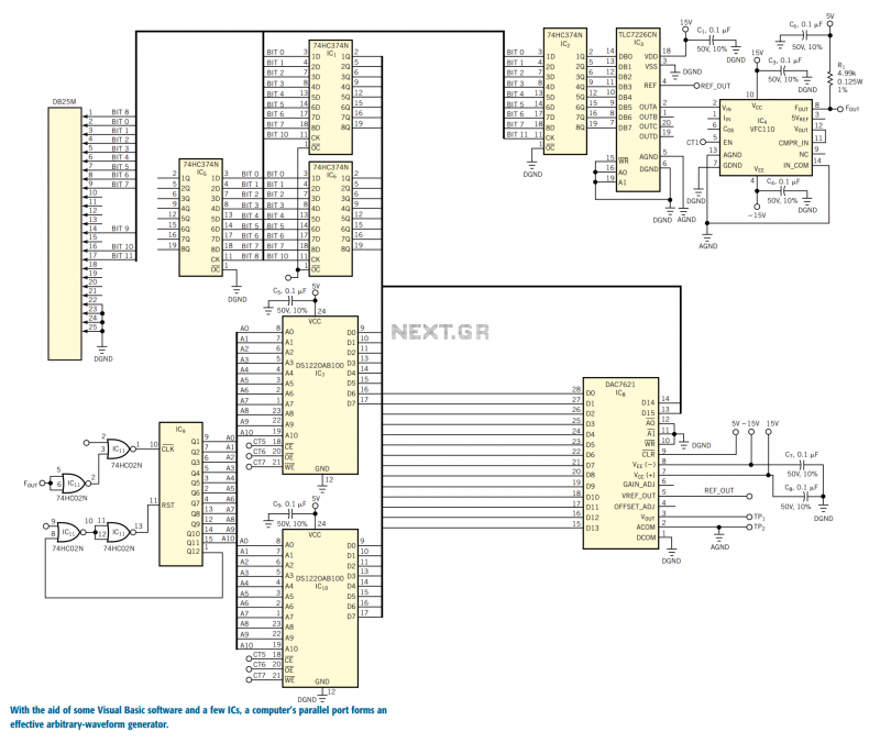
You can use the parallel port of your PC and a few additional components to generate a powerful, easy-to-use arbitrary-waveform generator. By using a Visual Basic program with the circuit in Figure 1, you can generate any waveform (for...
Below is a thermostat circuit I recently built to control a 1300 watt space heater. The heater element (not shown) is connected in series with two back to back 16 amp SCRs (not shown) which are controlled with a...
Figure 15-22 illustrates a doorbell system that consists of a monostable timing circuit, a password switch, a NAND gate circuit, and a sound output circuit. The operation of the circuit is designed such that when the password switch is...
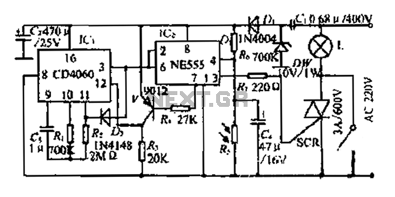
A photosensitive daytime electricity circuit utilizes a very small positive voltage. It features a 555 timer IC with four pins, including a reset pin that operates at low voltage. The circuit includes a bidirectional thyristor (iSCR) that controls lighting,...
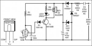
The following circuit illustrates an IR Remote Control Tester Circuit. Features include that transistor T1 conducts during the negative pulse period, and there is a data output pin. The IR Remote Control Tester Circuit is designed to verify the functionality...