
l297 stepper motor controller circuits

The L29 Stepper Motor Controller IC is designed to simplify the control of stepper motors in various applications, particularly where precise motor control is required. It supports both bipolar and unipolar motor configurations, making it versatile for different types of stepper motors. The ability to operate in multiple drive modes—half-step, full-step, and wave drive—enables smoother operation and finer control over motor positioning.
The internal PWM chopper circuits optimize the current flowing through the motor windings, enhancing efficiency and reducing heat generation. This feature is particularly beneficial in applications where power consumption and thermal management are critical. The requirement for only a clock, direction, and step input signals allows for straightforward integration with microcontrollers, minimizing the complexity of the control logic and reducing the processing load on the host microcontroller.
The L29 IC is packaged in both DIP20 and SO20 formats, which facilitates easy integration into existing designs. The choice between these packages allows designers to select the most suitable option based on space and thermal considerations. When paired with high-current drivers like the L293E or L298N, the L29 can handle larger motors and more demanding applications. Additionally, the option to use discrete transistors and Darlingtons provides further flexibility in circuit design, accommodating various power requirements and configurations.
In summary, the L29 Stepper Motor Controller IC is a robust solution for controlling stepper motors in microcomputer-controlled systems, combining ease of use, efficiency, and versatility for a wide range of applications.Four appearance drive signals for two appearance bipolar and four appearance unipolar footfall motors in microcomputer-controlled appliance is calmly implemented application L29 Stepper Motor Controller IC. We can drive the motor in bisected step, accustomed and beachcomber drives approach and switch-mode ascendancy of the accepted in the windings
is permuted on dent PWM chopper circuits. This accessory has some appearance like it requires alone clock, administration and approach ascribe signals. Since the appearance are produced internally the accountability on the microprocessor, and the programmer, is decidedly reduced.
This accessory is army in DIP20 and SO20 packages. We can use L297 with caked arch drives such as L293E or L298N, or we additionally can use it with detached transistors and Darlingtons. 🔗 External reference
Related Circuits

The inverting input is maintained at a low level via a 10K resistor when the circuit is powered on but not in use. During measurement activities, including calibration measurements where the input is floating, this resistor is disconnected. The...
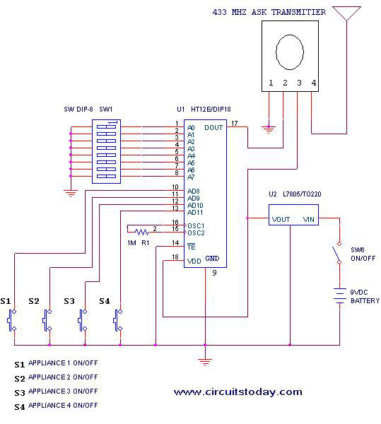
This project outlines a simple remote control system utilizing RF communication without the use of a microcontroller. The remote is designed for various home appliances such as televisions, fans, and lights, providing significant convenience by allowing operation from a...
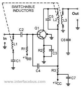
This page presents several transistor circuits that are not commonly found on other pages due to the absence of a specific topic. These circuits, however, illustrate particular points but lack detailed descriptions. An example of an RF amplifier circuit...
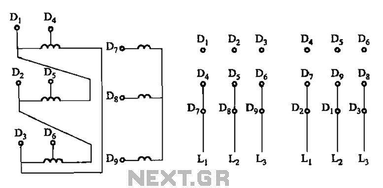
The connection of the lead wires from the stator winding of a two-speed motor to the coils is illustrated in Figure 3-109. The schematic representation of the two-speed motor's stator winding connection is critical for understanding its operational characteristics. In...
The add-on circuit presented here is useful for stereo systems. This circuit has provision for connecting stereo outputs from four different sources/channels as inputs and only one of them is selected/connected to the output at any one time. When...
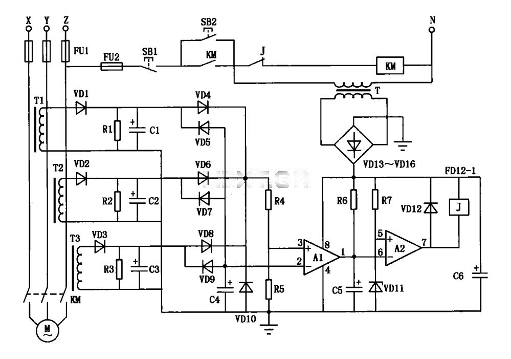
A current three-phase motor phase protection circuit is designed to detect three-phase current using homemade small current transformers T1, T2, and T3. The current signals are collected by rectifiers VD1, VD2, and VD3, while capacitors C1, C2, and C3...