
One Amp Battery Charger

The schematic diagram of the One Amp charger reveals that the AC mains connect to a transformer, which performs three main functions: voltage transformation, current limitation, and isolation. An iron core transformer may include air gaps within its laminations, which can reduce coupling between primary and secondary windings, thereby limiting the power available at the secondary. The circuit includes a switch to select the appropriate voltage for the battery being charged. The AC voltage from the transformer must be converted to DC for battery charging, which is accomplished by a diode that allows current to flow in one direction only. A thermal breaker is incorporated as a safety mechanism to interrupt current flow if it exceeds safe levels, thereby protecting both the battery and the charger from damage.
The charger employs a selenium rectifier, an older technology that continues to be utilized in modern equipment due to its unique characteristics beneficial for battery charging. The voltage drop across the selenium rectifier must be subtracted from the AC voltage to determine the effective voltage delivered to the battery. It is crucial for the output voltage of the charger to exceed the battery terminal voltage to facilitate current flow. If a silicon diode rectifier is used instead of a selenium rectifier, it will exhibit a lower voltage drop, resulting in a higher voltage delivered to the battery. However, silicon diodes lack the self-healing characteristics of selenium rectifiers, which necessitates the inclusion of a fuse or safety device to prevent damage to the rectifier when connecting to a deeply discharged battery.
Modern transformers can be utilized, but care must be taken to select one with appropriate impedance to avoid excessive current. Transformers designed specifically for battery charging often include built-in current limiting features. A low-value, high-power resistor can be added to manage surge capabilities, though it will introduce power loss and generate heat. The One Amp charger includes a modification in the form of a standard 0-1 mA DC meter, which was enhanced with a shunt made from copper magnet wire to read up to 1 amp full scale. This shunt allows most of the current to bypass the meter, ensuring accurate readings.
When connected to a battery, the One Amp charger demonstrates its effectiveness in restoring charge. The charger can be observed in operation, with readings indicating the battery state and charging current. As the battery charges, its terminal voltage increases, and the current drawn from the charger decreases, confirming the charging process is functioning correctly. Overall, this One Amp charger exemplifies a simple yet effective design for battery charging, highlighting the importance of modern component considerations in the construction of similar devices.When I purchased this little charger back in 1970 I didn`t think I`d be writing about it today but here we are! Back then I was a lot younger, I had an old car for transportation, and it had an old battery. It didn`t have a lot of cranking power when the weather turned cold, so I had to find a way to keep my wheels running.
This little charger was the answer to my problems. But I digress. What brings us here today is a friend of mine, asking how to build a battery charger. He tells me that he has a couple of transformers and wonders what else is needed to make one. Well that`s a pretty good starting point having a transformer, and there`s not much more required to complete the job. A charger for a car battery can be really very simple, as long as there is a human to monitor the charging process.
Cars and tractors have a Lead Acid wet cell battery, usually 6 or 12 volts. We`ll be looking at this Woodward-Schumacher Electric Corp. One Amp battery charger to get some ideas about what it takes to make one. I did a Google search and found Woodward-Schumacher is still in business designing and selling battery chargers. That is remarkable. To charge a Lead Acid battery is a fairly easy. DC current is driven into the battery from a controlled power source. Controlled to limit the current to a maximum level appropriate for the size of the battery, usually around 10% of the battery capacity.
A 100 Amp Hour battery would be 10 Amps maximum, but following the battery manufacturer`s recommendation is always the best option. This One Amp charger can charge a larger capacity battery, it will just take longer to get fully charged.
The simplicity of this charger is elegant because of these two parameters, however care must be taken by the person using a unit like this because the uncontrolled parameter istime. Leave the charger connected for too long and the electrolyte will start to boil away, which is a bad thing of course.
Electrolyte boiling begins around 14. 5 volts for a 12 volt wet cell battery. Deep cycle lead acid Absorbed Glass Matt (AGM) type RV or solar home battery (steady low current demand). Notice the charging voltage never gets to the boiling point. That`s by design to prevent electrolyte loss which is unrecoverable with a sealed battery. These are very general voltages because we`ve completely ignored temperature which will change these significantly.
Cold temperatures make these voltage points higher while warm temperatures make them lower by a few tenths of a volt. Here is a schematic diagram of what is inside the One Amp charger. The first thing that happens is the AC mains connect to a transformer which does three things: That third item is accomplished partially by #2, and the rest is a result of the AC impedance of the transformer itself.
An iron core transformer like this one can be built with an air gap, air spaces, between the lamination`s on the inside where you can`t see them. Air spaces tend to reduce coupling between primary and secondary winding therefore limiting the power available at the secondary where the battery will attach.
The circuit also has a switch for selecting the correct voltage for the battery to be charged. AC voltage on the secondary of the transformer needs to be changed into DC (Direct Current) appropriate for charging a battery which is naturally DC itself. That job is performed by the Diode, only allowing current to pass through it in one direction. The direction of the arrow points to the Plus (+) side of the battery. Next there is a Thermal Breaker. This is a temperature controlled circuit breaker which will open and stop current flow to the battery if the current is too high.
It is a safety device for protecting the battery and the charger from damage. After a short time period a Thermal Breaker will close the circuit and start current flowing into the battery again. The meter is reading 15. 81 volts AC. I think the Fluke 77 actually reads AVERAGE voltage, not RMS. RMS readings are more accurate for measuringsine wavevoltages, but this is close enough for us. The voltage shown here is reduced further by the drop across the rectifier changing the AC voltage to DC voltage for the battery.
The One Amp charger uses an older style rectifier called aselenium rectifier. It may be old technology but they are still used in new equipment today. These are interesting devices and have some unique characteristics which make them particularly desirable for use in a battery charger. A Google search turned up an interesting article written by Rich Bonkowski describing theselenium rectifierin easy to understand terms.
Here is what the selenium rectifier looks like in the One Amp charger. It`s about 1 1/2 inch square. We subtract the voltage drop across the rectifier from the AC voltage reading on the secondary of the transformer which brings us closer to the voltage rating of the battery. Keep in mind the voltage output of the charger needs to behigherthan the battery terminal voltage or there won`t be current flow into the battery.
Here`s what I measured for voltage drop across the selenium rectifier. Voltage vertical axis, current horizontal axis. Looks like the operating region will be around 1. 50 volts drop from the selenium rectifier. I connected a fairly dead battery to the One Amp charger and read about 0. 8 Amps on the meter resulting in about 1. 5 volts being dropped across the rectifier. I even made an attempt to take a picture of the waveform on the oscilloscope. I say attempt because it is an older analog Tektronix Scope with no photo capabilities at all. Here is what my old Sony camera did with it. It`s hard to see any graticule markings in the picture, but the scale is 5 volts per div (vertical) and 5mS per div (horizontal), sync is set to the line frequency. It shows about 17. 5 volts peak and this is with a 0. 8 amp load. What this tells us is the battery voltage would have to rise to17. 5 voltsfor the current to drop to zero. Ouch! If you will be using a silicon diode rectifier in place of a selenium device there will be less voltage drop which means higher voltage to the battery.
A silicon diode rectifier has a lower impedance than selenium resulting in higher current into the battery. Silicon diodes do not have the `self healing` ability that selenium does which means if you connect to a very dead battery you might end up frying the silicon rectifier.
Hence the need to have a fuse or some kind of safety limiting device to prevent this from happening. Modern transformers are OK to use, but a general purpose transformer may have a low impedance resulting in higher a current to the battery than your design. There are transformers designed for battery charger service which have built-in current limiting because of the air gaps within the iron core lamination.
A low value high power resistor would remedy this, and also soften the surge capability of the silicon diode, however it will introduce a source of power loss and will generate heat. This is usually anequitable trade offin the design when the transformer isn`t a perfect match. The meter seen on the top of the One Amp charger is a modification I added to it myself not long after I purchased it.
It`s a standard 0-1 ma DC meter. I made a shunt out of a small coil of copper magnet wire so it would read 1 amp full scale. The shunt passes most of the current, leaving a small amount for the meter. In the close up photo you can see the loop of wire above the coil. That is the half way point in the coil. Half of the coil is wound in one direction and the other half is wound in the opposite direction. The purpose of this is to make the coil nonmagnetic when current is passing through it. If the coil were wound in one direction only you would end up with an electromagnet which may affect the reading displayed on the meter. In any case, I have found the addition of the meter to be useful in helping determine if a battery is really dead or just needing to be topped off.
I attached the One Amp charger to a battery in my workshop and took some pictures of it in operation. The battery shown here is part of a bank of 12 volt AGM deep cycle batteries that I use for lights and other things.
They are not automotive cranking type batteries but will serve as a load for this demonstration. You can see the battery clips attached to the top of this 33 amp hour battery. The readings here show the battery charge state is a little low at 12. 61 volts, therefore is taking a little power from the charger. Charging current is 0. 9 amps. Fluke meter shows AC volts from the transformer at about 14. 01 volts, a little less than we saw above (15. 81 volts) with no battery connected. This is because the battery is accepting current during the charge which loads down the transformer output voltage. All of these readings look normal and acceptable. As the battery charges it`s terminal voltage goes up and the readings look a little different. Charge current decreases, transformer AC voltage output increases. The battery is clearly accepting the charge and on its way to being restored to full capacity. Well that about raps it up. This little One Amp charger has served me well over the years. As we`ve seen it is a pretty simple circuit to build. The use of modern general purpose components need to be considered when building a charger like this one.
Good luck with your design. 🔗 External reference
Related Circuits
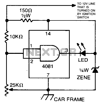
This circuit utilizes an LED and a 4081 CMOS integrated circuit. A variable resistor is employed to adjust the voltage threshold at which the LED activates. The control should be set so that the LED illuminates when the voltage...
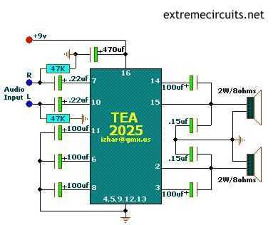
The above circuits are based on TEA2025, a monolithic integrated audio amplifier in a 16-pin plastic dual in-line package manufactured by UTC. The circuit has an internal thermal protector and is designed for portable cassette players and radios. It...
The circuit topology is similar to the previously mentioned amplifier, utilizing the robust IRFP240 and IRFP9240 MOSFET devices as the output pair, along with high-voltage Motorola transistors in the preceding stages. The supply rail voltage is conservatively set at...
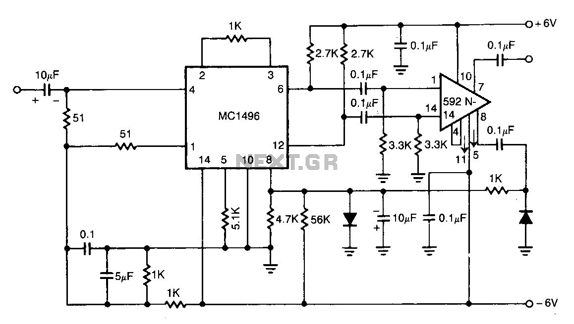
The NE592 is connected with the MC1496 balanced modulator to create an effective automatic gain control system. The signal is input to the MC1496 and then re-coupled to the NE592. Unbalancing the carrier input of the MC1496 allows the...
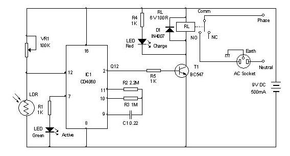
Timer for Charger Circuit Diagram. This timer circuit assists in maintaining the battery in optimal condition by enabling automatic charging for 5 to 6 hours daily, allowing the device to be left unattended. The timer circuit for the charger is...
Lead acid battery charger schematic using IC LM317. This lead acid battery charger circuit is simple to build and can be fit in a small box. The lead acid battery charger circuit utilizing the LM317 integrated circuit (IC) is a...