
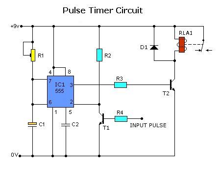
Timer for Charger

The timer circuit for the charger is designed to automate the charging process of a battery, ensuring that it remains in peak condition without requiring constant supervision. This circuit typically incorporates a timer IC, such as the 555 timer, which can be configured in monostable or astable mode depending on the desired functionality.
In a typical configuration, the timer can be set to initiate the charging cycle for a predetermined duration, usually between 5 to 6 hours. This is achieved by adjusting the resistor and capacitor values connected to the timer IC, which determine the time delay. Upon activation, the timer switches on a relay or a transistor, which in turn connects the battery to the charger.
The circuit may also include additional components such as diodes for protection against reverse polarity, capacitors for filtering, and resistors to limit current. A voltage regulator can be integrated to ensure that the battery is charged at a safe voltage level, preventing overcharging which can damage the battery.
Furthermore, an LED indicator can be added to signal the status of the charging process, providing visual feedback to the user. This timer circuit is particularly useful in applications where batteries are charged in remote locations or where user intervention is not feasible, thus enhancing the reliability and longevity of the battery system.
Overall, the timer for the charger circuit diagram exemplifies a practical solution for automated battery management, contributing to the efficiency and convenience of battery-operated devices.Timer for Charger Circuit Diagram. This timer circuit helps to keep the battery in top condition through automatic charging for 5 to 6 hours daily so that the instrument can be left unattended 🔗 External reference
Related Circuits
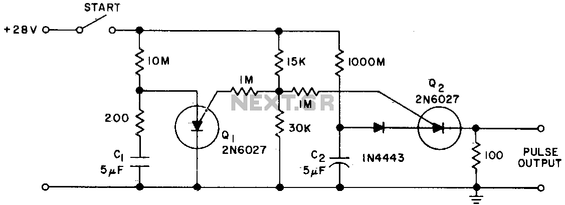
The Programmable Unijunction Transistor (PUT) serves as both a timing element and a sampling oscillator. A low leakage film capacitor is required for capacitor C2 because of the minimal current supplied to it. The Programmable Unijunction Transistor (PUT) is a...
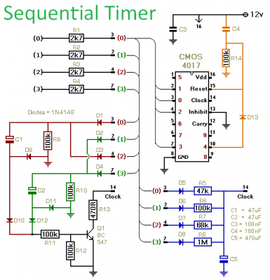
This timer is designed to manage a sequence of up to ten distinct events, with each event's duration adjustable independently. The sequence can either run for a predetermined number of cycles or continue indefinitely. Additionally, the individual events within...
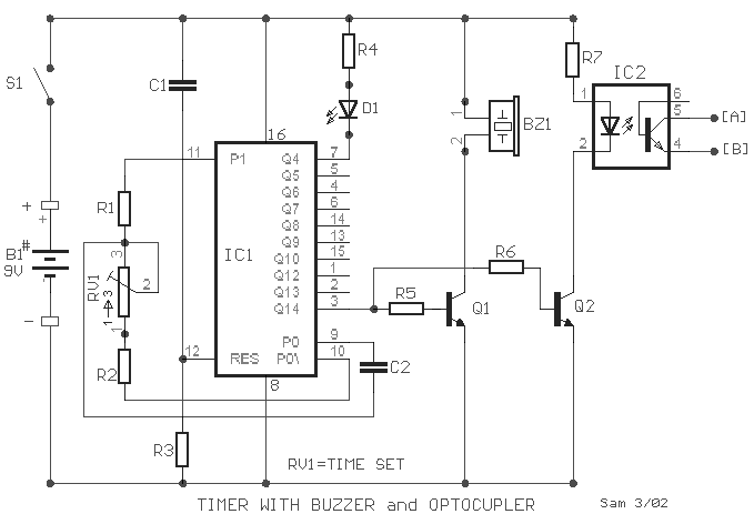
A small circuit designed for various time measurement applications. It features an audible sound signal from the buzzer BZ1 and has the capability to drive an external circuit through the optocoupler IC2, once the appropriate circuit is connected to...
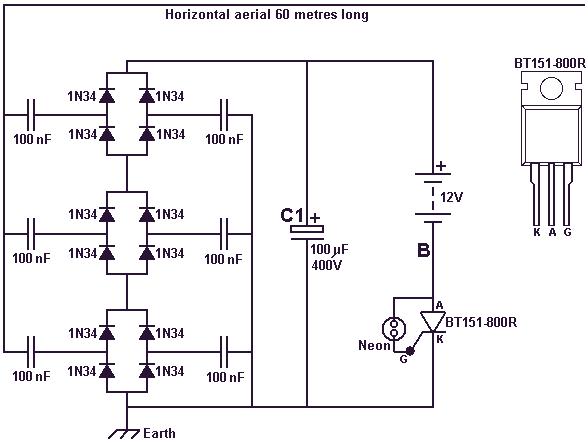
As the circuit operates, the three sets of diodes with their isolation capacitors build up an increasing voltage on capacitor C1. The voltage at point B will also increase and be about twelve volts less than the voltage on...
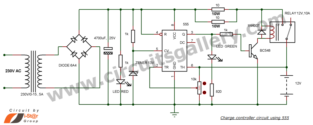
This is a simple DIY charge controller schematic created in response to a request from one of the readers on our Facebook page. The primary component of this automatic battery charger circuit is a 555 timer, which compares the...
Today, solutions are offered for a timed control relay that utilizes Normally Open (NO) and Normally Closed (NC) contacts to manage the operation of other devices, enabling or disabling them as needed. The functionality of this circuit is based...