
one ic two tones siren with

This circuit utilizes a combination of integrated circuits (ICs) to produce varied audio outputs suitable for a range of applications in toys and small vehicles. The primary components include operational amplifiers or logic gates configured to oscillate at specific frequencies. The sound generation is achieved through the interaction of IC1A and IC1B for the dual-tone siren, while IC1C and IC1D are responsible for the variable frequency siren sound.
The circuit's functionality is initiated by the user-operated switch SW1, which allows for easy toggling between the two sound modes. The use of potentiometer P1 enhances user interaction by enabling dynamic adjustments to the frequency of the old siren sound, providing an engaging experience for children.
The output stage, represented by Q1, serves as an audio amplifier, ensuring that the sound produced is loud enough to be heard clearly in outdoor environments. The selection of a suitable loudspeaker is critical; it should have an adequate power rating and be housed in a case that amplifies sound without distortion.
Capacitors C1, C2, C5, and C6, along with their associated resistors, form the timing components that dictate the frequency and duration of the sound waves generated. By modifying these components, designers can tailor the sound output to specific preferences or requirements, allowing for customization in various applications.
Overall, this circuit provides a fun and interactive audio experience, making it an ideal addition to children's toys and models, while also being energy-efficient by eliminating the need for a dedicated power switch.This circuit is intended for children fun, and can be installed on bicycles, battery powered cars and motorcycles, but also on models and various games and toys. With SW1 positioned as shown in the circuit diagram, the typical dual-tone sound of Police or Fire-brigade cars is generated, by the oscillation of IC1A and IC1B gates.
With SW1 set to th e other position, the old siren sound increasing in frequency and then slowly decreasing is reproduced, by pushing on P1 that starts oscillation in IC1C and IC1D. The loudspeaker, driven by Q1, should be of reasonable dimensions and well encased, in order to obtain a more realistic and louder output.
Tone and period of the sound oscillations can be varied by changing the values of C1, C2, C5, C6 and/or associated resistors. No power switch is required: leave SW1 in the low position (old-type siren) and the circuit consumption will be negligible.
🔗 External reference
Related Circuits
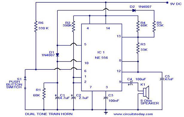
A dual-tone model train horn/sound generator/simulator circuit can be created using two NE 555 timers connected in cascade. However, the circuit diagram presented is designed with the NE 556 integrated circuit, which essentially comprises two 555 timers in a...

This approach utilizes a Hip-Hop, a shift register, and two gates (A). Before the one-shot pulse, the output of the NOR gate is 0. Consequently, the data input of the D-type flip-flop is equivalent to the trigger. When a...

By mixing an audio signal with ultrasound, it is possible to perceive the audio as if it originates from within the head, even when the 'headphones' are positioned far from the ears. Patrick Flanagan invented the "Neurophone" over 40...
This circuit generates a ringing sound akin to that produced by modern telephones. It comprises three nearly identical oscillators arranged in a sequence, each responsible for generating a square wave signal. The frequency of each oscillator is determined by...
This circuit utilizes a synchronous demodulator to extract a 1 kHz signal from noise and measures its amplitude, with the 1 kHz signal providing a resolution of approximately 60 microvolts per count. The measurements are transmitted via an RS-232...
This circuit will flash a bright LED 5000mcd as an intention getting device or fake car alarm. More: Component values are not critical and different transistors may be used. This circuit functions as a visual alert system by utilizing a...