
One Receiver

The described receiver circuit is an exemplary project for electronics enthusiasts, particularly those interested in vintage technology. The use of the 6AF11 compactron vacuum tube is significant, as it integrates multiple amplification stages into a single package, simplifying the overall design. The regenerative detector configuration enhances sensitivity, allowing the receiver to pick up weaker signals effectively. The audio amplification stages ensure that the output is strong enough to drive both headphones and a speaker, providing flexibility in listening options.
The incorporation of plug-in coils facilitates easy frequency adjustments, allowing the user to adapt the receiver for different bands without extensive rewiring. The variable capacitors (C2 and C3) are essential for achieving precise tuning, which is critical for effective short-wave reception. The design's versatility in antenna coupling enhances the receiver's performance, enabling users to optimize selectivity based on their specific operating environment.
The construction of the receiver emphasizes accessibility, with all components mounted on a chassis that allows for straightforward assembly and troubleshooting. This design choice is advantageous for beginners, as it minimizes the complexity associated with traditional receiver builds. Additionally, the thoughtful layout ensures that all components can be tested before final assembly, reducing the likelihood of errors during the building process.
Overall, this compact receiver design serves as an excellent introduction to the world of radio electronics, combining vintage technology with practical construction techniques. It offers a rewarding project for hobbyists and provides a functional tool for exploring the radio spectrum.RF Cafe visitor David M. wrote to ask that I scan and post this article from the January 1963 edition of Popular Electronics. It is an article written by Philip Hatfield, of the Receiving Tube Department of General Electric that describe a very simple design that uses a " compactron " vacuum tube, which consist of two triodes and a pentode. The compactron was sort of a vacuum tube version of the multi-amplifier integrated circuit of today. They are still available for purchase on eBay for a couple bucks each. MOST of today`s short-wave receivers are truly sensitive and reliable devices, but they are also rather complex and expensive for the beginner to construct. Here`s a simple receiver, using one compactron tube, that will give you long-wave, broadcast-band, and short-wave reception.
If you are considering putting your first receiver together, this one is for you. If you, have an amateur-band-only receiver, this unit will fill in some of the "holes" in the spectrum. Finally, if you already have a general-coverage receiver, this set will make a good "auxiliary" to tuck a way on a corner of the desk just in, case your "big" one quits.
Use of a compactron allows a lot of receiver to be contained in a small box without undue crowding. the frequency range covered is from 250 kc. all the way to 16 mc. ; and, since plug-in coils are used, it`s possible to extend the range in either direction. Plenty of headphone volume is provided, and many signals will operate the built-in speaker in a very satisfactory manner. The Circuit. The 6AF11 compactron contains two triodes and a pentode. One triode is used a regenerative detector, the other as an audio voltage amplifier, and the pentode as an audio power amplifier.
Plug-in coils containing primary (L1), secondary (L2), and tickler (L3) windings determine the frequency range. Tuning is done with a relatively large variable capacitor (C2) to allow covering a wide range of frequencies with a minimum of coils.
For fine tuning, a small variable capacitor (C3) is connected in parallel with the larger one to act as a "vernier. " The antenna coupling circuit is purposely designed for versatility. Straight inductive coupling, series tuning, or parallel tuning are possible, depending on the connections to jacks J1, J2, and J3 (see antenna hookup diagram).
This can be quite helpful in increasing the selectivity of the receiver and in tuning out the "dead spots" that afflict most regenerative receivers. For maximum audio output, the headphones are operated from the pentode section of the compactron, and the phone jack (J4) is arranged to disconnect the speaker when the phones are in use.
The Receiver. All parts of the receiver, with the exception of the spare-coil rack, and the trap door for coil changing, are mounted on the portion of the chassis box used to form the front panel and sides. As the photos show, this makes all parts of the receiver readily accessible to the builder. In addition, since no electrical components are mounted on the removable portion of the box, all the testing that is necessary can be done before the cabinet is "buttoned up.
" To reduce sheet metal bending to a minimum, the chassis proper is a fiat plate, cut to make a fairly snug fit, and then fastened in place with four small angle brackets. All mounting holes should be cut in this plate and the chas sis box before the plate is bolted in place.
After the holes have been drilled, all of the parts should be mounted, since they are all readily accessible for wiring in any sequence. In mounting the 40p. p. f. antenna tuning capacitor (C1), flat washers should be 🔗 External reference
Related Circuits

The circuit expands a single 15-pin D-sub VGA output to multiple outputs, allowing for the connection of up to six monitors simultaneously. The input VGA connector is positioned on the left side, while the six output VGA connectors are...

The circuit presented utilizes modulated rectangular waves of varying time periods to generate ringing tones akin to those produced by a telephone. It requires four astable multivibrators for operation, implemented using two 556 integrated circuits (ICs). The 556 IC...
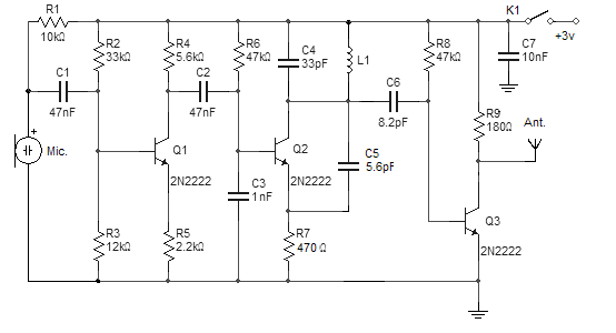
This FM wireless microphone is straightforward to construct and offers significant transmission capabilities, with a range of approximately 300 meters outdoors. Its compact component count and 3V operating voltage allow it to effectively penetrate multiple floors of an apartment...

A decision has been made to construct a microphone preamplifier and tone control circuit that was featured on another website. The equalization section is identical to the one used in the... This microphone preamplifier and tone control circuit is designed...
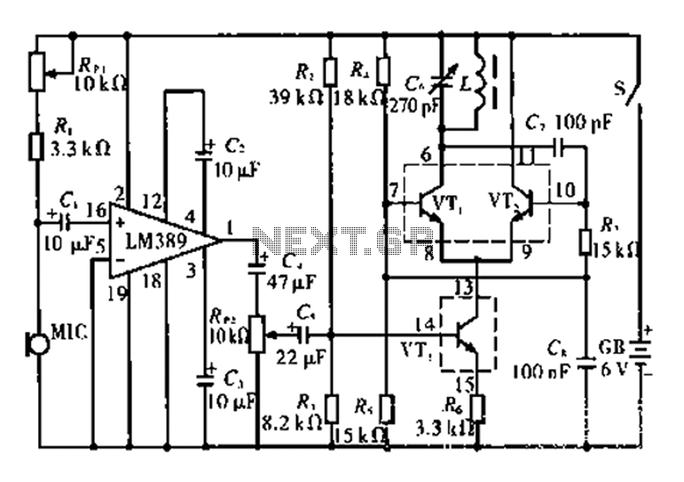
This circuit is tested and functional. The LM389 integrated circuit serves as the core element, where the voice channel number is acquired by the microphone (MIC) and converted into electrical signals. These signals are amplified by the volume control...
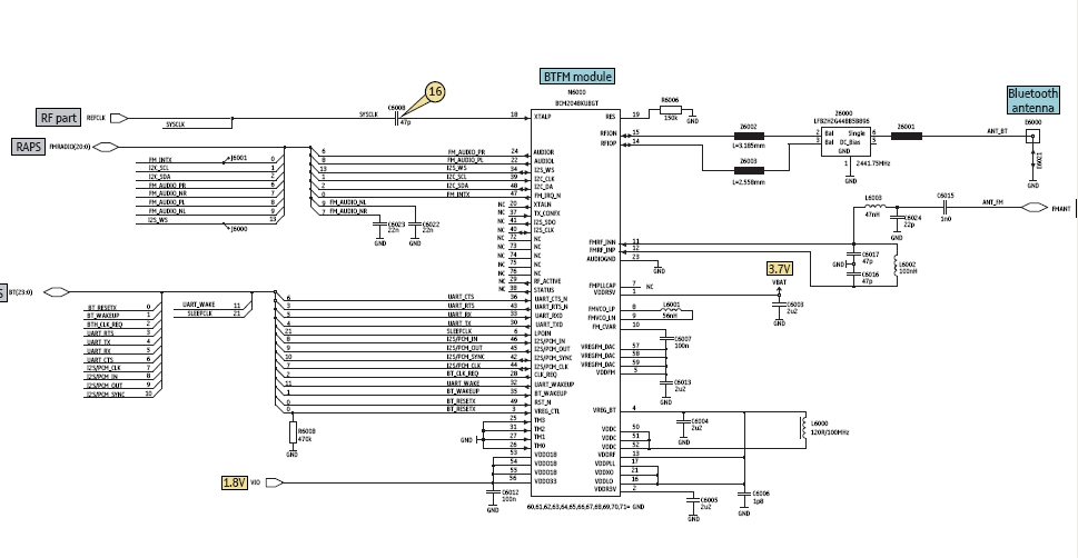
Bluetooth is an open wireless technology standard for exchanging data over short distances between fixed and mobile devices, utilizing short wavelength radio transmissions to create personal area networks (PANs) with high security. The Bluetooth baseband protocol combines circuit and...