
One simple second pulse source circuit

The described circuit operates as a relaxation oscillator, utilizing the single-junction transistor VTi to generate a time-dependent output. The resistor Ri plays a crucial role in setting the base biasing of VTi, while the capacitor C charges and discharges, creating oscillation. The potentiometer RP is integral to frequency adjustment; by varying its resistance, the charge and discharge time of capacitor C is modified, thereby altering the frequency of the oscillation. This allows for a flexible output pulse width, enabling the system to produce time base pulses between 0.1 seconds and 15 seconds.
The output from the relaxation oscillator is fed into the amplifier transistor VTz, which boosts the signal strength of the generated square wave pulse. This amplified output is critical for driving subsequent circuits, such as a time counter, ensuring that the pulse is adequately strong to be detected and processed. The overall design is efficient for applications requiring variable timing signals, making it suitable for timing applications in various electronic systems. The simplicity of the components involved allows for easy assembly and adjustment, making it a practical solution for generating controlled time intervals.It consists of single-junction transistor VTi, resistance Ri, potentiometer RP, capacitor C consisting of relaxation oscillator and amplifier transistor VTz. Adjustment potentiometer RP, can change the relaxation oscillation frequency to give 0. 1 ~ 15s time base pulse. After this pulse by VTz amplified output square wave pulse, as the time counter input signal.
Related Circuits
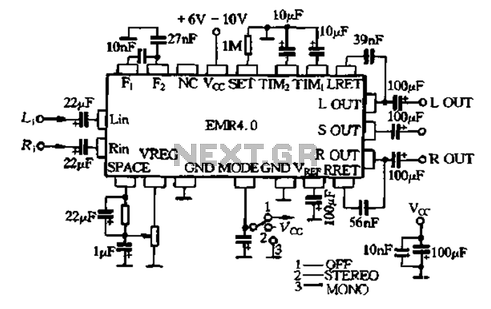
The EMR 4.0 operates with a single power supply ranging from 6V to 10V, with an optimal supply voltage of 9V. It requires effective power filtering to minimize noise, particularly when there is no signal input. The quiescent current...
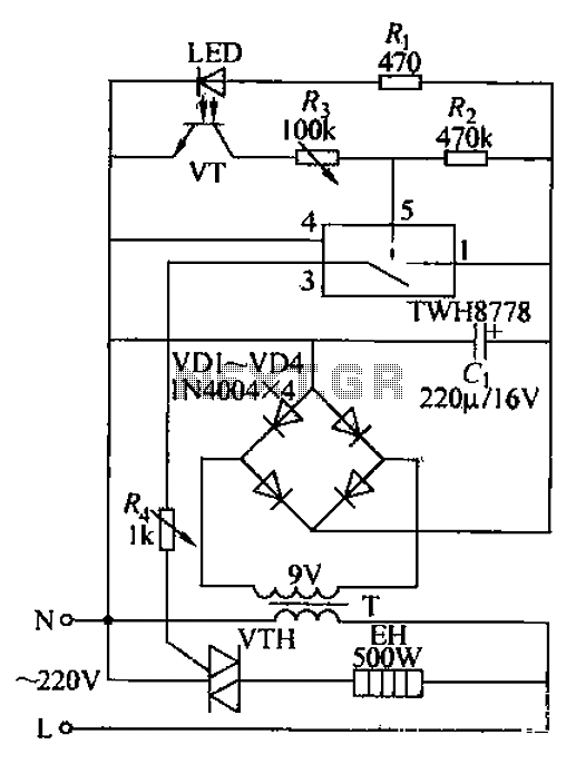
Bathroom automatic hand dryer circuit. The circuit features an LED and a photosensitive transistor (VT) that together form an infrared opto coupler, serving as a signal sensing mechanism. The control element is a 1WH8778 switch integrated circuit. When hands...
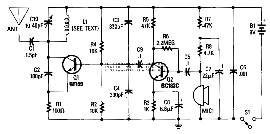
An adjustable capacitor C10 and a coil L1 create a tank circuit that, along with Q1, C2, and R1, oscillates at a frequency within the FM band. The center frequency is adjustable by tuning C10. An electret microphone, M1,...
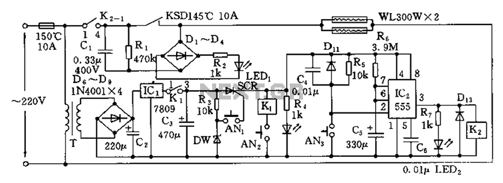
The disinfection cabinet circuit operates on the principle of using infrared heating within a closed cabinet to create a high-temperature environment for disinfecting tableware. The circuit includes an AC buck regulator, an infrared heating circuit, and a timing control...
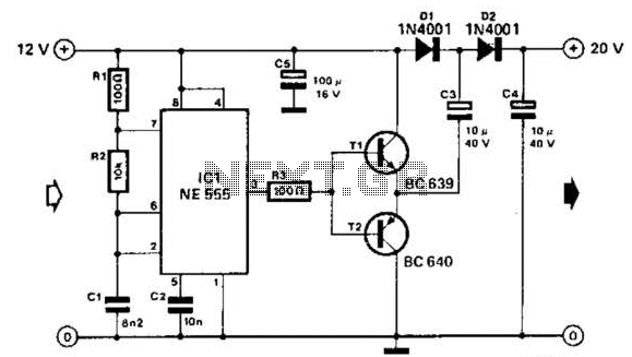
Using a 555 timer and voltage doubler, this circuit will supply over 50 mA at 20 V DC. Transistors T1 and T2 act as power amplifiers to drive the voltage doubler. The frequency of operation is approximately 8.5 kHz. The...
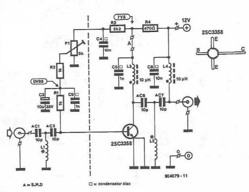
This UHF amplifier circuit project is beneficial for enhancing weak TV signals. The amplifier provides a gain of 10-15 dB within a frequency range of 400 to 850 MHz. To ensure optimal performance and reliability, the PCB tracks should...