
One thyristor incandescent dimming circuit

The thyristor incandescent dimming circuit is a sophisticated electronic control system designed to manage the brightness of incandescent lamps by regulating the power delivered to the load. The core component of this circuit is the thyristor, which functions as a controlled rectifier. It allows current to flow through the load only when triggered, effectively controlling the average power delivered to the lamp.
In the configuration shown in Figure 2-66 (a), the circuit incorporates a half-wave control method. The thyristor is connected in series with the lamp, and a diode is used to provide additional control and protection. The adjustment potentiometer RP is crucial for varying the voltage across the lamp, enabling fine-tuning of the brightness. By adjusting RP while the switch SA is set to position "3," users can achieve a voltage range from 20V to 100V, allowing for a broad spectrum of brightness levels.
Switch SA has three positions, each corresponding to a different brightness setting. In position "2," the circuit limits the power to the lamp to approximately 1/4 of its rated capacity, providing a significant reduction in brightness for applications requiring lower light levels. Position "1" allows full power to the lamp, ensuring maximum brightness.
Figure 2-66 (b) simplifies the design by employing only a thyristor for dimming control, suitable for a 110V rated bulb. This design emphasizes the versatility of thyristors in controlling incandescent lighting while maintaining efficiency and reliability. The circuit's design can be adapted for various applications, from residential lighting to industrial settings, where precise light control is essential. Overall, this thyristor-based dimming circuit exemplifies an effective solution for managing incandescent lamp brightness with ease and precision.(1) using thyristor incandescent dimming circuit one circuit is shown in Figure 2-66. Figure 2-66 (a) using thyristor half- wave controlled dimmer and dimmer with diode approach. When the switch SA hit when "3" position, the adjustment potentiometer RP, the voltage across the lamp varies from 20-100V; when SA hit the "2" position, the light bulb brightness light-emitting rated power of about 1/4; when SA hit the "1" bits set when, all light bulbs. Figure 2-66 (b) using only product thyristor dimmer, use rated voltage lloV bulb.
Related Circuits

The PGA202 is a digitally controlled programmable gain amplifier with gain settings of G = 1, 10, 100, and 1000. The PGA203 offers gain settings of G = 1, 2, 4, and 8. Both amplifiers are compatible with CMOS...

An even power device is designed to supply energy to a computer. It is typically intended for converting alternating current (AC) into low-voltage direct current (DC). Without this component, a computer is merely a collection of metal and plastic...

This simple circuit can monitor the overflow of water from the overhead tank. The sensor placed close to the lid of the overhead tank continuously monitors the presence of water. The described circuit functions as a water overflow monitoring system...
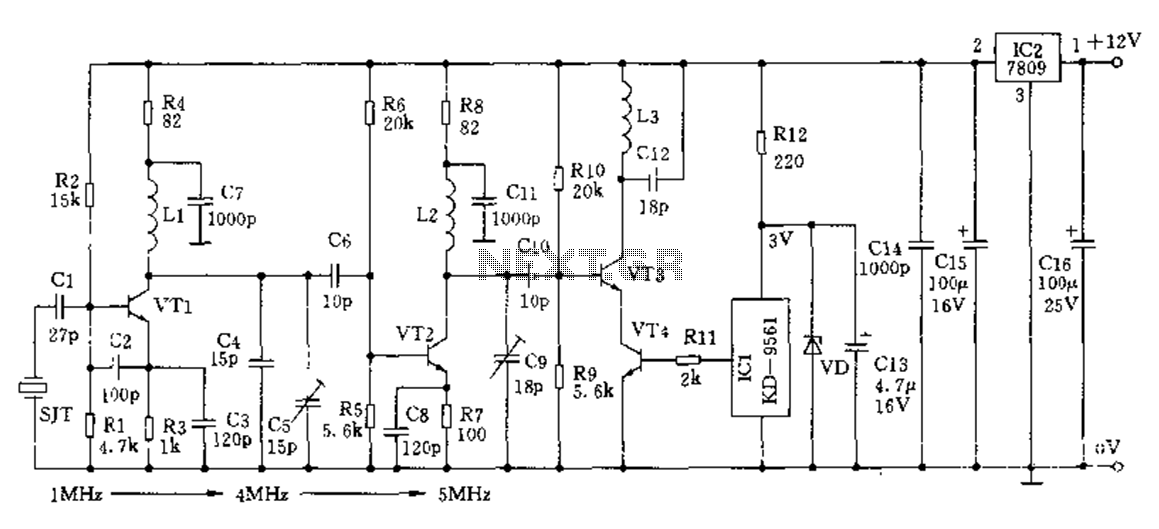
The crystal frequency stabilization of a frequency modulation circuit is illustrated below. The frequency modulation (FM) circuit utilizes crystal frequency stabilization to ensure precise frequency control and stability. This process involves the use of a quartz crystal oscillator, which...
This simple circuit tests speakers, microphones, transformers, and voltage. It is essentially a very low-frequency oscillator that produces extremely short pulses. The sound produced is easy to hear and helps determine the precise direction it originates from, making it...
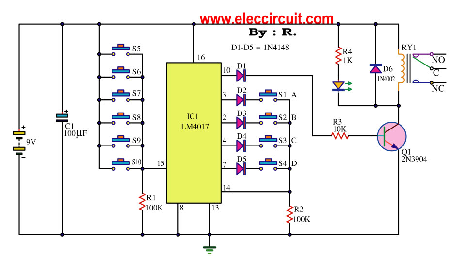
This key code switch circuit is an electronic circuit designed to replace conventional key switches, eliminating the need for physical key inserts. The key code switch circuit utilizes a microcontroller or a dedicated integrated circuit (IC) to interpret key codes entered...