
Overflow Indicator Circuit

The described circuit functions as a water overflow monitoring system for overhead tanks, utilizing a water level sensor to detect the presence of water at a predefined level. The circuit typically includes a water level sensor, a microcontroller or comparator circuit, and an alert mechanism such as a buzzer or LED indicator.
The water level sensor, often a float switch or capacitive sensor, is installed near the top of the tank. When water reaches the sensor's threshold level, it triggers a signal to the microcontroller. The microcontroller processes this input and activates the alert mechanism, notifying users of the overflow condition.
In a typical implementation, the circuit may also incorporate a relay module that can control a valve or pump to prevent overflow by stopping water inflow. Power supply considerations are crucial; the circuit may operate on a low voltage DC source, ensuring safety and efficiency.
Additional features may include a manual reset button, a display for indicating water levels, and a wireless module for remote monitoring. Overall, this circuit provides an effective solution for managing water levels in overhead tanks, preventing overflow and potential damage.This Simple circuit can monitor overflow of water from the Overhead tank. The sensor placed close to the lid of the overhead tank always monitor the presen.. 🔗 External reference
Related Circuits
This is a programmable alarm timer circuit that uses LEDs to indicate hours and minutes. Twelve LEDs can be arranged in a circle to represent the 12 hours of a clock face, and an additional 12 LEDs can be...
The automatic toilet flusher is designed to restructure the traditional flushing mechanism, allowing for a single, reliable flush after each use. It features energy-saving capabilities and a long-lasting chip, ensuring ease of use even when disconnected from the power...
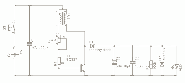
For the past few days, research has been conducted on an intriguing boost circuit known as the Joule Thief. The original schematic can be found through online resources. The Joule Thief is a simple yet effective boost converter circuit designed...
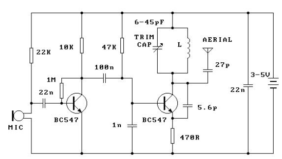
This FM transmitter circuit is very simple and has acceptable transmission. The signal transmitted from this FM transmitter circuit can be received at almost 300 meters in open air. The circuit requires a 3-volt operating voltage and can be...
This is a straightforward infrared detector circuit designed to detect infrared light. The circuit comprises only three components: an RS-276-145 photo transistor, a 330-ohm resistor, and a general-purpose LED (Light Emitting Diode). When the photo transistor receives infrared light...
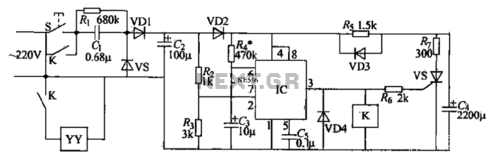
555 low power timing circuit diagram. The diagram is from the technical information of Chinaicmart. For more detailed information about the circuit diagram. The 555 timer IC is widely utilized in various applications due to its versatility and ease of...