
One transistor code lock

The electronic code lock circuit operates on the principle of using a transistor as a switch, which is controlled by the state of multiple input switches. The arrangement of the switches is crucial for ensuring that the correct combination is required to activate the relay. The series connection of switches S0 to S4 allows for a high signal at the base of the transistor only when all these switches are closed (ON). Conversely, the parallel configuration of switches S5 to S9 ensures that the transistor remains OFF when any of these switches are closed (ON).
The relay serves as the output mechanism, allowing for the control of a larger load, such as a door lock or an alarm system, based on the state of the transistor. The power supply section, comprising the transformer (T1), bridge rectifier (D1), and capacitor (C1), converts the AC voltage from the mains to a suitable DC voltage required for the operation of the circuit. The freewheeling diode (D2) protects the transistor from voltage spikes generated when the relay coil is de-energized, which could otherwise cause damage to the transistor.
Resistor (R1) plays a vital role in ensuring that the transistor does not inadvertently turn ON due to noise or floating voltages at the base when the switches are not engaged. The design allows for flexibility in the arrangement of the switches, enabling customization of the lock code while maintaining a straightforward implementation. This circuit is ideal for applications requiring simple access control mechanisms, providing a reliable and efficient solution for electronic locking systems.This is of course the simplest electronic code lock circuit one can make. The circuit uses one transistor, a relay and few passive components. The simplicity does not have any influence on the performance and this circuit works really fine. The circuit is nothing but a simple transistor switch with a relay at its collector as load. Five switches ( S0 to S4) arranged in series with the current limiting resistor R2 is connected across the base of the transistor and positive supply rail. Another five switches (S5 to S9) arranged in parallel is connected across the base of the transistor and ground.
The transistor Q1 will be ON and relay will be activated only if all the switches S0 to S4 are ON and S5 to S9 are OFF. Arrange these switches in a shuffled manner on the panel and that it. The relay will be ON only if the switches S0 to S9 are either OFF or ON in the correct combination. The device to be controlled using the lock circuit can be connected through the relay terminals. Transformer T1, bridge D1, capacitor C1 forms the power supply section of the circuit. Diode D2 is a freewheeling diode. Resistor R1 ensures that the transistor Q1 is OFF when there is no connection between its base and positive supply rail.
🔗 External reference
Related Circuits
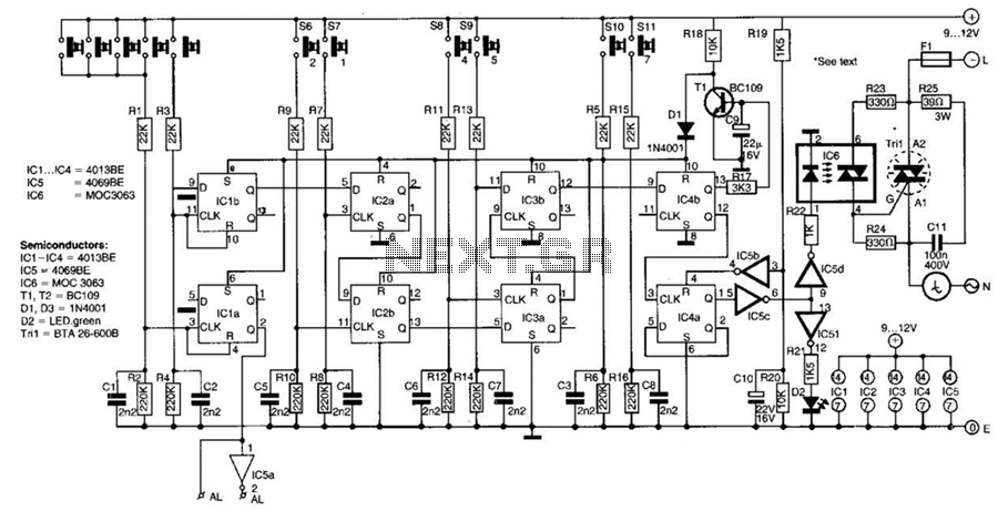
This switch utilizes four CD4013BE dual flip-flops, an inverter, and an optoisolator to control a triac, allowing it to switch a 25-A AC load current. A standard 4x3 telephone keypad is employed for entering a 6-digit code. In the...
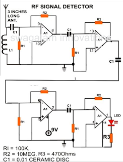
A simple electronic circuit project is presented that can be constructed by any school student for display at a school science fair. The proposed circuit is a high-gain operational amplifier (op-amp) amplifier designed to detect the slightest RF disturbances...
The locker alarm circuit, also known as the cashbox watcher, is designed to safeguard a cashbox or locker from unauthorized access. This reliable design features a foolproof, remotely operated alarm and electromagnetic relay driver that receives its control signal...
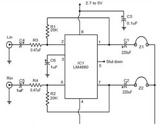
The LM4880 is a dual audio HiFi amplifier integrated circuit from National Semiconductor. This headphone amplifier circuit is specifically designed to produce high-quality audio output with a minimal number of components. The LM4880 integrated circuit is capable of delivering...
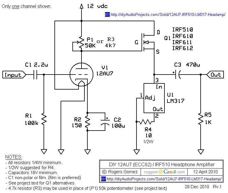
The NP-100v12 is a straightforward headphone amplifier designed for entry-level builders to assemble and listen to their own creation. The term "builder" refers to individuals with electronic experience and innovation, allowing them to create a device rather than merely...
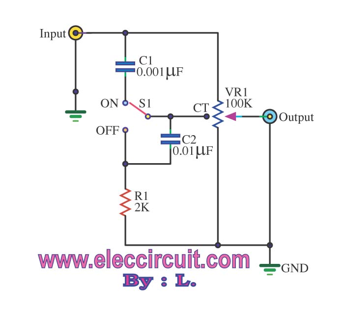
The passive tone control circuit is designed to adjust the bass without expansion, utilizing resistors (R) and capacitors (C). It functions as a frequency filter and is easy to construct, requiring no external power supply. This circuit can be...