
One Transistor Pump Building Block

The single transistor pump circuit utilizes a transistor as the primary active component to control the flow of current. Typically, this circuit is designed to convert a low input voltage into a higher output voltage, effectively functioning as a voltage booster. The simplicity of the design makes it an excellent choice for educational purposes and for prototyping in various electronic applications.
In its basic form, the circuit consists of a transistor (usually an NPN type), a few passive components such as resistors and capacitors, and a load. The transistor operates in its active region, where it amplifies the input signal. A resistor is connected to the base of the transistor to control the base current, which in turn regulates the collector current flowing through the load.
The operation of the circuit can be enhanced by incorporating a feedback mechanism. For instance, a capacitor can be used to store charge and smooth the output voltage, providing better performance under varying load conditions. Additionally, a diode may be included in the circuit to prevent backflow of current, ensuring that the pump function remains effective.
This circuit can be adapted for various applications, such as driving small motors, powering LED arrays, or serving as a power supply for low-power devices. By modifying component values or adding additional stages, the circuit can be tailored to meet specific voltage and current requirements, making it a versatile building block in electronic design.This is a one transistor pump circuit. This is a very simple circuit and very helpful, you can use it as a building block for designing more complex electronic.. 🔗 External reference
Related Circuits
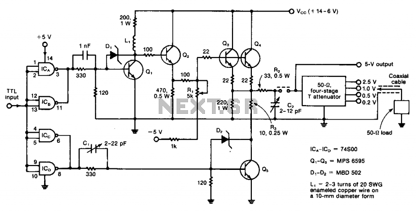
The circuit operates from DC to 50 MHz and is capable of delivering pulses as short as 10 ns. It is driven by a TTL signal through a 740S00 quad Schottky NAND gate, with input connections made via ICA...
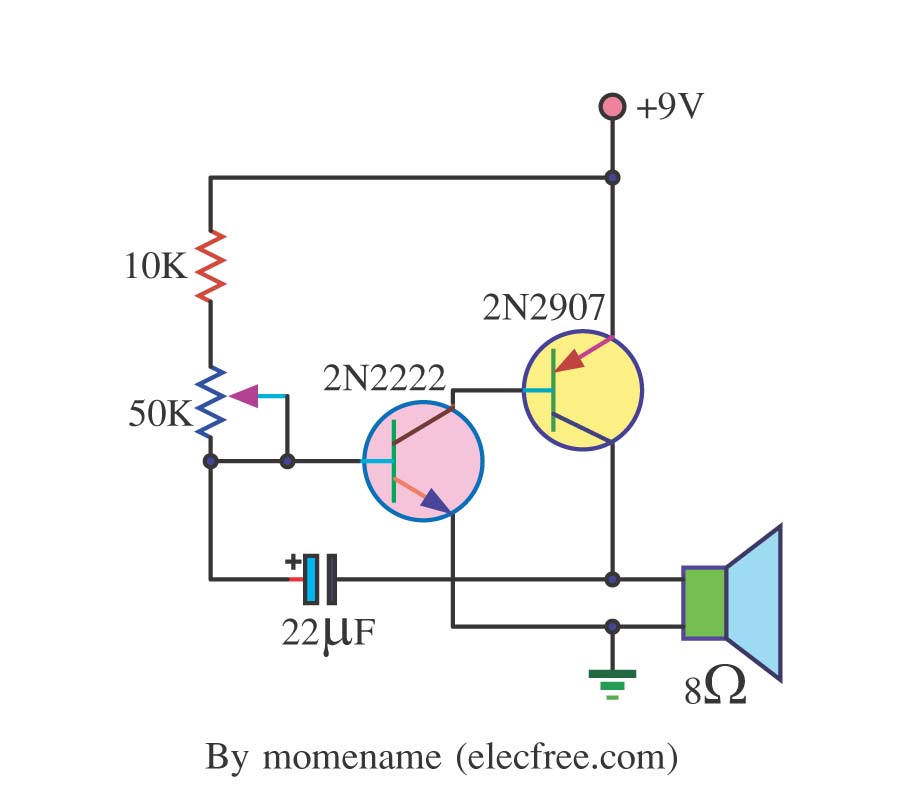
This is a simple tone oscillator generator. It uses the transistors 2N2222 and 2N2907 as the main components. The tone sound is controlled with a 50K ohm resistor (R2) and an 8-ohm speaker is utilized. The tone oscillator generator circuit...
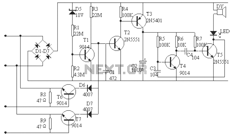
The phone alarm device is designed to monitor and prevent unauthorized use of a telephone line. When interference signals are detected on the line due to theft attempts, the alarm activates, preventing the thief from making calls while alerting...
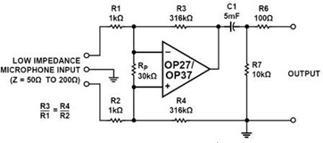
A simple but effective fixed gain transformerless microphone preamplifier circuit diagram is shown in the picture below. The circuit amplifies differential signals from low impedance microphones by 50 dB and has an input impedance of 2 kOhms. The OP27/37...
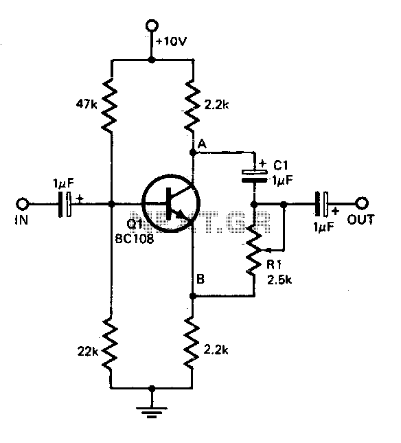
This circuit offers a straightforward method for achieving phase shifts between 0° and 170°. The transistor functions as a phase splitter, with the output at point A being 180° out of phase with the input. Point B remains in...
Currently, there is a growing trend to utilize telephone lines for long-range control and alarm systems within transmission mediums, which is accompanied by extensive research. Such systems typically consist of alarm devices and police notification arrangements, including a central...