
Telephone line burglar alarm circuit diagram

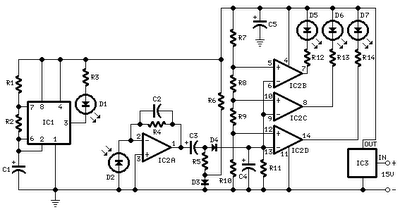
When the telephone line is tampered with, the external voltage drops to about 9V, preventing D5 from breaking down. Consequently, T1 does not receive bias and cuts off, causing T2's base potential to rise and allowing T2 to conduct. This activation turns on T3, which drives the audio-stage oscillation circuit, LED, and DY audible alarm. The LED and DY generate an interference signal on the external line, making it impossible for the thief to complete a call and forcing them to hang up. Although the owner can answer the phone, which reduces the voltage and turns off T1, transistors T6 and T7 (used for ease of installation and allowing polarity-independent connection) still provide base current through the telephone line, ensuring T3 remains off and the oscillation circuit is inactive. This design allows the owner to make normal calls without disruption, as the resistance between the master telephone and the external line (R8, R9) is minimal, ensuring no interference during calls. The electronic components used in the telephone line burglar alarm circuit include general-purpose diodes D1-D4 (e.g., IN4007), an 18V regulator for D5, and a 3V electromagnetic buzzer for DY. Carbon film resistors rated at 1/8W are recommended for the resistances, along with other components as specified in the schematic.
The operational principle of this phone alarm device relies on the monitoring of line voltage and the behavior of the transistors and diodes under varying conditions. The design ensures that the system remains inactive during normal operation while providing robust protection against unauthorized access. The use of common electronic components not only simplifies the construction of the circuit but also makes it cost-effective and easily accessible for implementation. By integrating an audible alarm and visual indicators, the device effectively alerts the owner to potential theft while maintaining the integrity of regular telephone service.Phone alarm device can monitor and prevent unlawful misappropriation of your telephone line. When someone in your telephone line and the machine thefts from outside the alarm on the issue of interference signals, so thieves can not dial, and the light was stolen phone to the owner Tip Sound. The following figure is a schematic diagram of the anti-theft device, usually the post office sends program-controlled machine outside line standby voltage of about 60V, the D1-D4 is positive polarity switch on top, D5 breakdown by R2 enable T1 base potential rises, T1 guide pass, T2 cutoff, T3 is turned off, the oscillation circuit consists of T4, T5 composition does not work. When the phone theft elevator, outside the voltage drop of about 9V, can not make D5 breakdown, T1 because no bias cut, T2 base potential rise conduction.
T2 is turned on so T3 is turned on and driven by the audio-stage oscillation circuit, LED, DY audible alarm, and through the LED, DY interfering signal plus an outside line, while the external voltage is low, so that person can not be stolen phone dial-up and forced to hang up. Although the owner pick up the phone to reduce the voltage, and T1 is turned off but the T6 or T7 (with T6, T7 two tubes for ease of installation, the line can access, regardless of polarity, D6, D7 isolators) by telephone machine to obtain the base current conduction, the T3 is not conducting an oscillation circuit does not work.
Therefore, the owner can dial the normal call is not affected. Because then there is only a very small resistance value between the master telephone with an outside R8, R9 so that when the phone call zero vibration are not affected. Telephone line burglar alarm circuit diagram Selection of electronic components D1-D4, D6, D7 can be used as general IN4007 rectifier, etc., D5 choice about 18V regulator, DY is 3V electromagnetic buzzer.
Resistance can be used carbon film resistor 1 / 8W, and other elements of the model shown in the illustration selected.
Related Circuits
This is a compact, easy-to-build amplifier that utilizes a single integrated circuit (IC) to deliver 40 watts of audio power. It is well-suited for amplifying audio signals from devices such as mobile CD players or iPods. The integrated circuit...
All distances mentioned can vary depending on the infrared transmitting and receiving LEDs used and are significantly affected by the color of the reflecting surface. Black surfaces greatly reduce the device's sensitivity. This circuit can also be applied in...
When this thermometer is utilized in a room environment, it operates intermittently, maintaining this operational state within the temperature measurement circuit due to the stable internal temperature. The astable multiresonance oscillator is composed of transistors VT1 and VT2, forming...
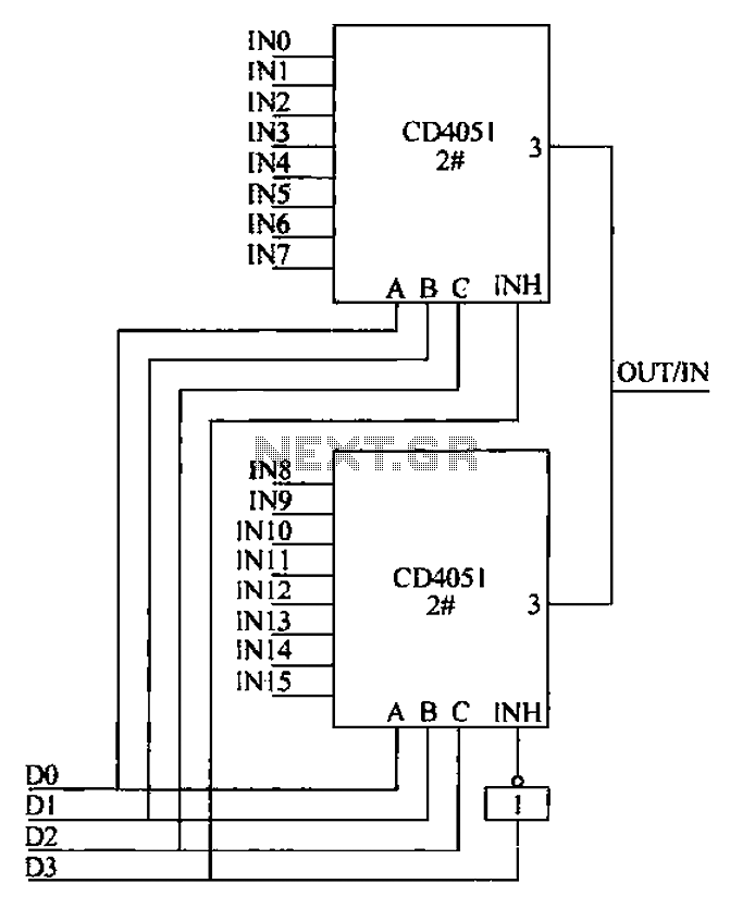
The CD4051 is a single-ended input 8-channel multiplexer that features three channel select inputs (A, B, C) and an inhibit input (INH). The signals at inputs A, B, and C are utilized to control the selection of one of...

An FM radio generates an interference signal that can be detected on another FM radio tuned 10.7 MHz higher than the original. A 50 kΩ potentiometer is used to adjust the modulation level to its maximum without introducing distortion....

The adjustable power supply can be reconfigured by changing the value of V2 and enhancing other components as needed. The output voltage is calculated using the formula Vnm = 1.25 (1 + R2/R^). Additionally, R2 can be modified as...