
One Winding Joule Thief circuit

The Cree 1 Watt LED High Power Joule Thief Kit is designed to demonstrate the principles of energy harvesting and efficient power conversion. The Joule Thief circuit is a simple yet effective boost converter that allows the extraction of usable voltage from low-voltage sources, such as single-cell batteries. This kit is particularly useful for educational purposes, as it provides hands-on experience with basic electronics and power management concepts.
The schematic for the Joule Thief circuit typically includes a few key components: a transistor, a resistor, an inductor (or transformer), and a diode. The transistor acts as a switch that rapidly turns on and off, allowing current to flow through the inductor. When the transistor is turned off, the magnetic field in the inductor collapses, inducing a higher voltage that is rectified by the diode and used to power the LED.
In the case of the Cree 1 Watt LED, the circuit is optimized to provide sufficient current and voltage to drive the LED efficiently. The Joule Thief circuit can operate with input voltages as low as 0.5V, making it suitable for use with depleted batteries or other low-voltage energy sources. The use of high-quality components, such as the Cree LED, ensures that the output light is bright and energy-efficient.
The Joule Thief Simulation II Graph provides a visual representation of the circuit's performance, illustrating the relationship between input voltage, output voltage, and current draw. This simulation can be used to analyze the efficiency of the circuit and to make adjustments to component values for optimization.
Overall, the Cree 1 Watt LED High Power Joule Thief Kit serves as an excellent introduction to power electronics, showcasing the principles of energy conversion and the practical applications of low-voltage circuits.Introducing the Cree 1 Watt LED High Power Joule Thief Kit. Joule thief Simulation II Graph and Schematic 🔗 External reference
Related Circuits
This schematic represents an FM transmitter capable of delivering an output power between 3 to 3.5 W, operating within the frequency range of 90 to 110 MHz. While the stability of the circuit is acceptable, the integration of a...
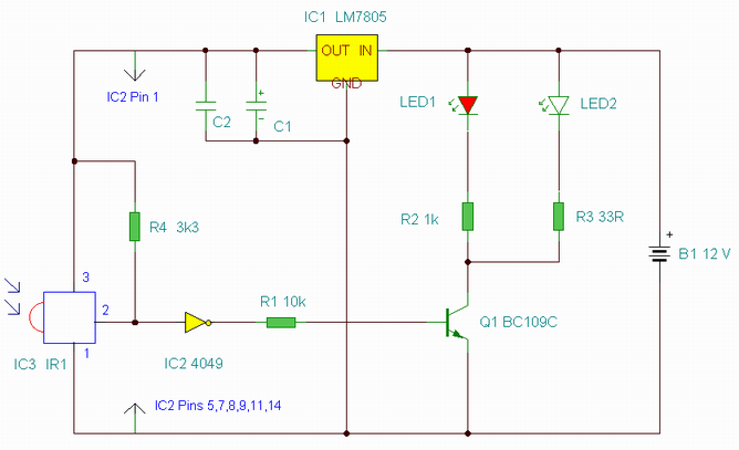
This is an enhanced infrared (IR) remote control extender circuit. It features high noise immunity, resistance to ambient and reflected light, and an increased operational range. The improved IR remote control extender circuit is designed to extend the range of...
A distortion circuit is being developed utilizing a single 12AU7 tube configured as a diode. The design is acknowledged as basic, intended primarily for the purpose of adding distortion effects. The proposed circuit leverages the 12AU7 vacuum tube, which is...
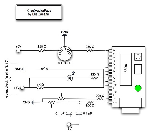
A few nice MIDI controller interfaces were discovered. The Knee(Audio)Pads are a wearable MIDI device. The MIDI controller interfaces mentioned provide innovative solutions for music production and performance. The Knee(Audio)Pads, in particular, represent a unique advancement in wearable MIDI technology....
It was observed that balls were becoming lodged in the ball trough, failing to load into an upkicker or not resting correctly on the trough ball microswitches or optos, which caused the machine to register a missing ball. Initially,...

A CMOS logic gate is utilized in this circuit. When an object approaches the antenna, the change in oscillator output is detected by components 1)1 and 1)2, which is then amplified by U1C. This amplification drives Q1, activating alarm...