
Proximity Alarm Ii Circuit

The circuit employs a CMOS (Complementary Metal-Oxide-Semiconductor) logic gate configuration, which is known for its low power consumption and high noise immunity. The primary function of the circuit is to detect the presence of an object near an antenna, which serves as a proximity sensor.
When an object comes within range, it causes a variation in the oscillator output. This change is detected by two components labeled 1)1 and 1)2, which likely represent specific sensor elements or input stages of the circuit. The detection mechanism is crucial as it translates the physical presence of an object into an electrical signal.
The detected signal is then fed into an amplification stage represented by U1C. This component is essential for boosting the signal strength, ensuring that it is sufficient to trigger subsequent actions in the circuit. The amplification process is critical in environments where the initial signal may be weak or prone to noise interference.
Following amplification, the output drives a transistor, Q1, which acts as a switch. When Q1 is activated, it allows current to flow to the alarm system, represented by BZ1. This alarm may be a buzzer or other alerting mechanism, providing an audible signal to indicate that an object has been detected.
The overall design of the circuit highlights the integration of analog and digital components to create a responsive detection system. The use of CMOS technology ensures efficiency, while the combination of detection, amplification, and actuation stages allows for reliable operation in various applications, such as security systems, automation, and proximity sensing. A CMOS logic gate is used to make up this circuit. When an object is near the antenna, the change in oscillator output is detected by 1)1 and 1)2 and amplified by U1C, which drives Ql, sounding alarm BZ1.
Related Circuits
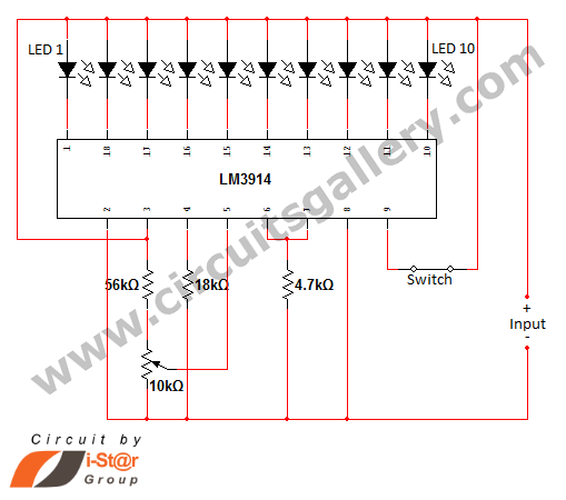
In various situations, it is necessary to indicate the amount of battery charge using methods such as LED dot displays or LED bar displays. This circuit utilizes the LM3914 integrated circuit to serve as a battery charge indicator with...
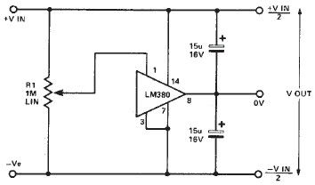
A simple split power supply circuit can be designed using the schematic diagram based on the LM380 audio power integrated circuit (IC). The output voltage regulation is dependent on the circuit feeding the LM380. The power dissipation is approximately...
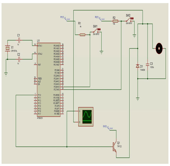
The objective of this project is to control the speed of a DC motor. The primary benefit of utilizing a DC motor is the ability to modify the Speed-Torque relationship to nearly any desired form. To facilitate speed control,...
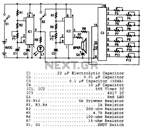
Three integrated circuits (ICs) are utilized to generate sounds. IC1 is a 555 timer configured as an astable multivibrator, producing clock pulses. The frequency of these clock pulses is adjustable via a trimmer potentiometer, P1. These clock pulses are...
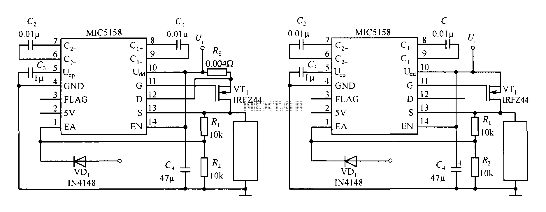
The MIC5158 is part of a high-speed switching circuit diagram that focuses on the rising edge. The MIC5158 is a precision voltage reference and high-speed switching device that is commonly utilized in various electronic applications requiring rapid signal transitions. In...
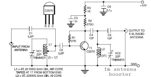
This is a low-cost FM antenna booster that can be used to listen to programs from distant FM stations clearly. The antenna FM booster circuit comprises a... The FM antenna booster circuit is designed to enhance the reception of FM...