
onoff 24 hours timer circuit schematic

The CMOS 4060 is a versatile integrated circuit that combines a binary counter and an oscillator, making it suitable for various timing applications. The counter operates by counting the oscillations generated by the oscillator circuit. The oscillator is formed by the two inverters and the passive components R3, R4, R5, and C3, which determine the frequency of oscillation. The output frequency can be finely tuned through R4, allowing for precise timing control.
The ten output pins of the counter can be utilized to indicate the current count, enabling the design of digital clocks, timers, and frequency dividers. The ability to switch the transistor via the output pins allows for the control of larger loads, such as relays, which can be used to switch on or off various devices in response to the counter's state.
In single-shot mode, the configuration with diode D1 prevents further oscillations once the desired count is reached, making it ideal for applications requiring a one-time event trigger. Conversely, by excluding D1, the circuit can operate in a continuous mode, providing a repetitive output signal that can be used for applications such as pulse-width modulation or regular timing signals.
The CMOS 4060's flexibility and ease of use make it a valuable component in electronic designs, allowing engineers to create efficient and reliable timing solutions in a compact form factor.The Cmos 4060 is a 14-bit binary counter. However - only ten of those bits are connected to output pins. The 4060 also has two inverters - connected in series across pins 11, 10 & 9. Together with R3, R4, R5 and C3 - they form a simple oscillator. While the oscillator is running - the 14-bit counter counts the number of oscillations - and the stat e of the count is reflected in the output pins. By adjusting R4 you can alter the frequency of the oscillator. So you can control the speed at which the count progresses. In other words - you can decide how long it will take for any given output pin to go high. When that pin goes high - it switches the transistor - and the transistor in turn operates the relay. In single-shot mode - the output pin does a second job. It uses D1 to disable the oscillator - so the count stops with the output pin high. If you want to use the timer in repeating mode - simply leave out D1. The count will carry on indefinitely. And the output pin will continue to switch the transistor on and off - at the same regular time intervals.
🔗 External reference
Related Circuits
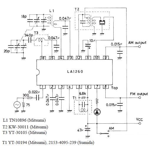
A very simple FM IF MW radio receiver circuit can be designed using the LA1260 IC manufactured by Sanyo Semiconductor. This FM IF MW radio receiver circuit schematic shows that the LA1260 IC can be utilized in AM and...
This project involves an automatic street light or lamp circuit designed to activate outdoor lights, such as garden lamps and night lights, automatically at sunset and turn them off at sunrise. The circuit is sensitive and versatile, capable of...
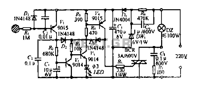
Diagram 2 depicts a shake tube circuit with a capacitance (C) and a trigger voltage rectifier filter element. The circuit includes a trigger voltage transistor amplifier (H), three pull tubes (n, U, v), and utilizes a thyristor as a...
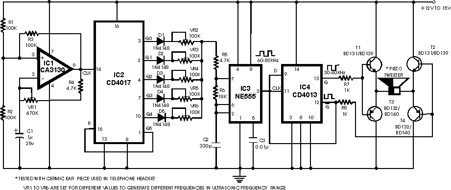
There are many ultrasonic pest repellent devices available on the market, but a major drawback is that their power output is low and their effectiveness suffers. Ultrasonic pest repellent devices utilize high-frequency sound waves to deter pests such as rodents...
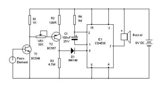
A vibration sensor or piezoelectric vibration sensor circuit diagram. It emits a loud beep when an attempt is made to break a door or window. The alarm automatically ceases after three minutes. The circuit utilizes a piezo element as...
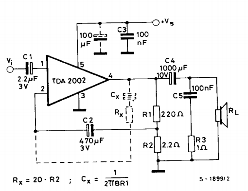
This is a power amplifier circuit built using the TDA2002 power amplifier IC module. It serves as a replacement for the original LM383, which is no longer available. The circuit is easy to assemble and requires a minimal number...