
op amp Op amp analysis question

The circuit under discussion is based on an operational amplifier configured to operate as a comparator or oscillator. The design employs a feedback mechanism that relies on the comparison of a dynamic input voltage $V_0$ with a stable reference voltage of 2.5 V generated by a square wave oscillator. The amplitude of this square wave is 5 V, which plays a crucial role in determining the output behavior of the circuit.
In this configuration, the operational amplifier's inverting and non-inverting inputs are pivotal for its functionality. The non-inverting input can be influenced by external voltage sources to create necessary asymmetry, which is essential for oscillation. By introducing a 10 MΩ resistor to ground or rail, or by momentarily applying a voltage to the non-inverting input, the circuit can be made to oscillate or switch states effectively.
The phase relationship caused by the RC links within the circuit is significant. Each RC network introduces a delay that contributes to the overall phase shift. When the cumulative phase shift reaches 180°, conditions for positive feedback are satisfied, potentially leading to sustained oscillations. This is a critical point for simulation, as it is essential to observe how the circuit responds to various input stimuli, such as a 3 Hz square wave applied to the inverting input.
The presence of two distinct DC paths from the output of the operational amplifier back to the inverting input raises concerns about the circuit's design. The precise values of these resistors—1.5 MΩ and 56.2 kΩ—impact the feedback and overall stability of the circuit. The time constant of approximately 0.1 seconds suggests that the circuit may exhibit a relatively slow response, which could affect its performance in high-frequency applications.
In conclusion, this circuit's design merits careful scrutiny, especially regarding its feedback configuration and component values. The operational amplifier's behavior, influenced by external voltage sources and the inherent RC delays, plays a crucial role in determining whether the circuit functions as intended or if it exhibits erratic behavior due to potential misconfigurations or design flaws.The circuit was reverse engineered from an old equipment. The op amp stage seems to me like a comparator/oscillator, it is comparing $V_0$ which varies over time because of the capacitors against the 2. 5[V] that is a square wave generatorwith 5V amplitud. So is this an square wave oscillator or what What is its output your problem with simulation arises because SPICE calculates the operating point and
brings up the circuit in an ideal state. You can add some asymmetry into the circuit via a large 10Mohm to ground or rail, OR you can bump the non-inverting input with a voltage source 100 ns into the sim. Starrt it at say 5 v and then kick it to 2. 5V and it should light up if you have it connected properly. placeholder Jan 28 `13 at 2:25 Since each RC link entails a phase delay, at the frequency where the total phase shift is 180 °, there ought to be some positive feedback.
What happens in your simulation if you start by force-feeding a 3 Hz square wave at the inverting input for a few seconds and then take it away Henning Makholm Jan 28 `13 at 2:41 The circuit is probably wrong, even though you have checked :-). You have 2 DC paths from U1A _out tp inverting input - one is 1. 5M and the other is 86. 2K (so precise). If it was positive feedback it would be interesting. Time constants are about 0. 1s. Overall it was either a rubbish circuit or intended to mislead or it has been reconstructed wrongly. | What is it part of Russell McMahon Jan 28 `13 at 2:43 @Russell McMahon: It is not 86. 2k but 56. 2k it was a measure straight from the Ohmeter. Ok, let`s suppose it is wrong and it is as you say but let`s concentrate on the given circuit arrangement (I`m open to suggestions and guesses of course).
Can`t tell if rubbish or misleading, maybe the inputs of op-amp are inverted, but then again let`s concentrate on the current circuit shown. Thanks. mongoose85 Jan 28 `13 at 2:55 🔗 External reference
Related Circuits
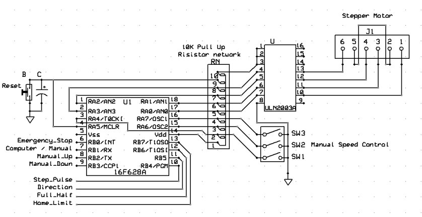
The inquiry was focused not only on power consumption but also on the observation that some stepper motors have more wires than the standard four, while others are classified as bipolar. Stepper motors are widely used in various applications due...
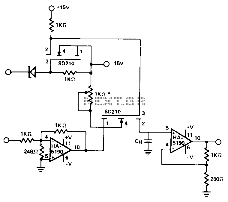
This circuit utilizes the speed and drive capability of the HA-5190 in conjunction with two high-speed DMOS FET switches. The input amplifier is configured to operate at a gain of -5, while the overall circuit gain remains at unity....
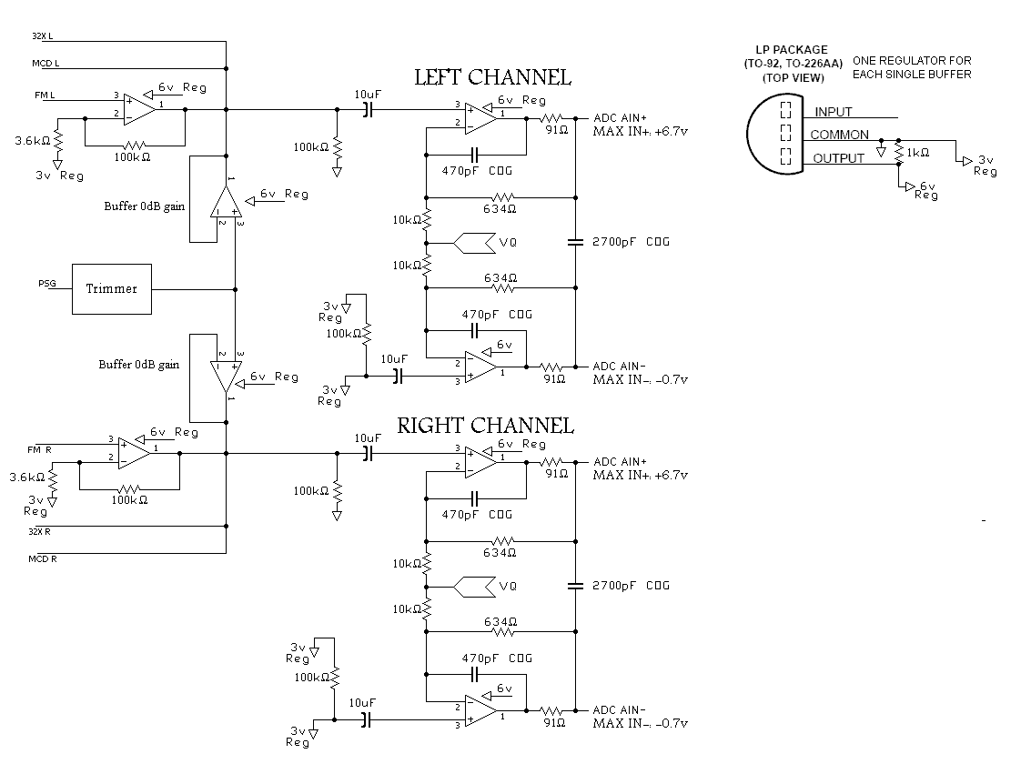
A program is needed to set the channels to their maximum level or to write the full scale to the Digital-to-Analog Converter (DAC). The MD schematics indicate that the audio signals are mixed with ratios of 0.0431 for the...
For several years, a rear fog lamp has been mandatory for trailers and caravans to enhance visibility in foggy conditions. When the fog lamp is activated, the fog lamp of the towing vehicle must be turned off to prevent...
It is important to note that there is limited protection circuitry and fuses in this amplifier. A short turn-on delay for the output power supply is included to minimize thumps, along with a couple of line fuses, but no...
For many applications, there's no substitute for sheer power - low efficiency speakers, outdoor sound systems, or maybe you like the full flavor of the dynamic range of a high power amp. Whatever your requirement, this super power module...