
stepper motor question

Stepper motors are widely used in various applications due to their precision control and ability to maintain position without requiring feedback systems. The conventional four-wire stepper motors are typically unipolar, meaning they have a center tap connected to the power supply, allowing current to flow in one direction through each coil. This configuration enables simpler control circuits but limits the torque and efficiency compared to bipolar stepper motors.
Bipolar stepper motors, on the other hand, utilize two coils without a center tap. These motors require more complex control circuits, often involving an H-bridge configuration that allows current to flow in both directions through the coils. This design increases torque and efficiency, making bipolar motors suitable for applications that demand higher performance.
When examining stepper motors, the number of wires can indicate the motor type and its operational characteristics. For instance, a five-wire motor typically indicates a unipolar design with a common connection, while a six-wire motor can be either unipolar or bipolar, depending on how the coils are configured. Understanding these distinctions is crucial for selecting the appropriate motor for specific applications, as it impacts not only power consumption but also control complexity and performance.
In summary, the choice between unipolar and bipolar stepper motors is influenced by factors such as wiring configuration, power requirements, and desired performance characteristics. Proper analysis of these elements is essential for effective motor selection in electronic designs.The reason i was asking more so than just the power consumption was the fact that some stepper motors seem to have more wires than the four that i have and other stepper motors are called bipolar. 🔗 External reference
Related Circuits
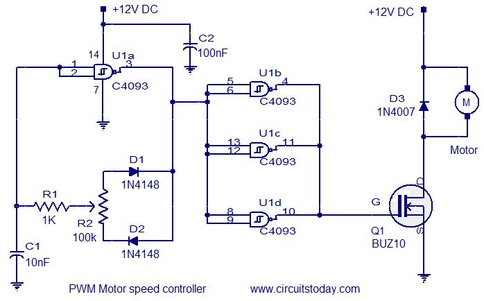
This circuit is designed based on a request from Mr. Vinoth in India. The requirement is for a 12V/5A DC fan motor controller. The circuit utilizes the quad 2-input Schmitt trigger IC CD4093 as its core component. Among the...
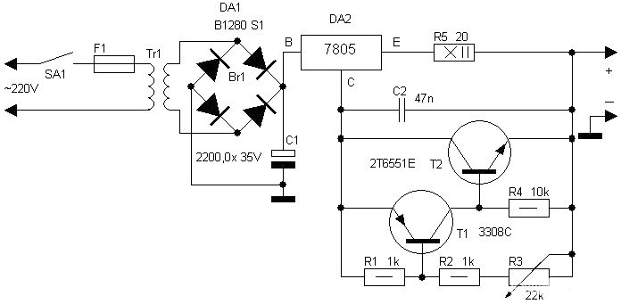
Motorcycle battery charger power supply. Refer to the mentioned page for an explanation of the power supply related circuit diagram. The description of the battery charger indicator: The circuit above enhances the appearance of a simple battery charger, making...
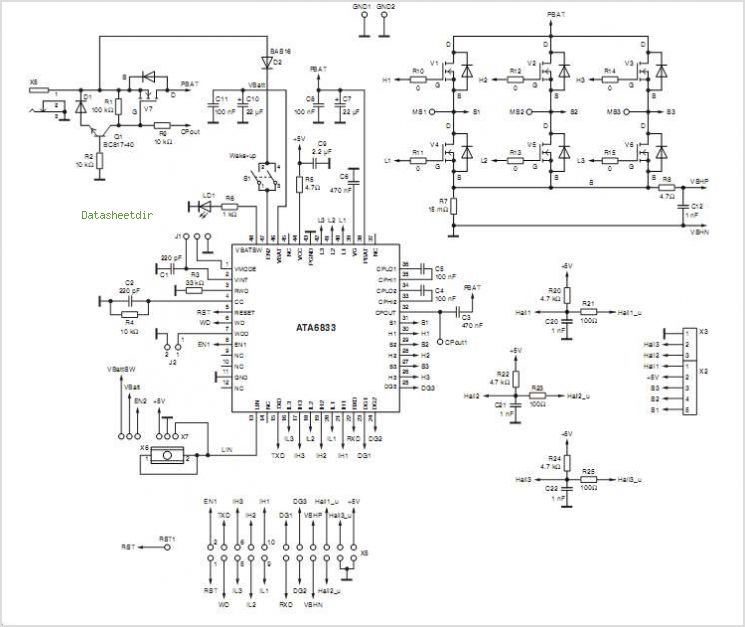
The T7024 is a single-supply front-end integrated circuit (IC) specifically designed for applications within the 2.4 GHz to 2.5 GHz frequency band. This front-end configuration includes a Power Amplifier (PA), a Low-Noise Amplifier (LNA), and a switch driver for...
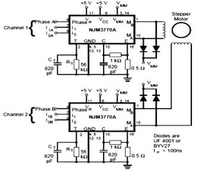
The schematic below represents a typical stepper motor driver application utilizing the NJM3770A. As illustrated in the diagram, the single-channel stepper motor drivers NJM3717 and NJM3770A operate independently and are not synchronized. The circuit design features the NJM3770A, a dedicated...
This integrated circuit is highly efficient and does not require any external glue logic for operation. It features two pins for motor control: one pin is dedicated to controlling the direction of the motor, while the other pin is...
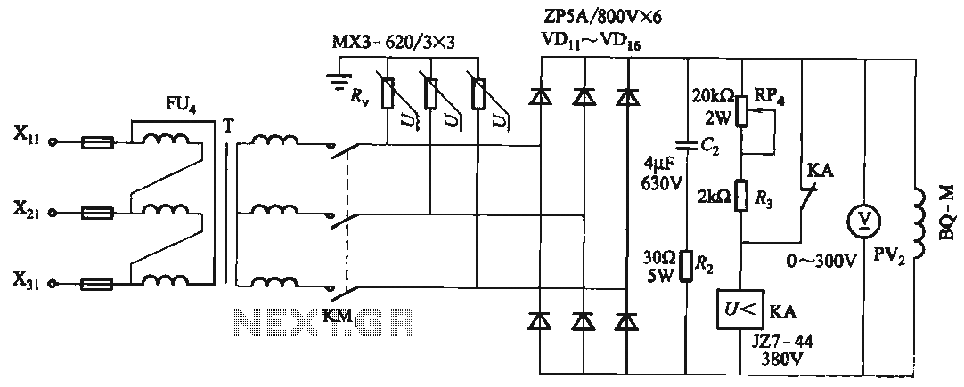
FIG T is the excitation transformer, R is a varistor, and there are rectifier diodes to protect against breakdowns from VDii to VD16; Rz and C2 provide resistive-capacitive protection. The circuit is designed to absorb voltage from the magnetic...