
Op Amp Power Driver

The operational amplifier (op-amp) output current limitations often necessitate additional circuitry when interfacing with loads such as small motors or loudspeakers. The conventional method of using an emitter follower, while effective in some cases, does not fully exploit the available supply voltage due to inherent voltage drops. Specifically, the output voltage of the op-amp is constrained to be 1 to 2 volts below the supply voltage (±Ui), compounded by the base-emitter voltage drop across the transistors used in the circuit.
To address these challenges, a more efficient circuit design is proposed, which leverages the output current of the op-amp to control driver transistors (T1 and T2). This design allows for a more effective use of the supply voltage, resulting in improved performance when driving small motors. The configuration is illustrated in both principle and practical diagrams, emphasizing its suitability for applications requiring higher output current.
In this circuit, the op-amp's output current is routed through its supply lines, allowing for the driver transistors to be activated via these lines. The inclusion of base-emitter resistors R4 and R5 is critical, as they ensure that T1 and T2 remain inactive in the presence of quiescent currents from the op-amp. Furthermore, resistor R6 serves to limit the output current from the op-amp, providing an additional layer of protection. In cases where the op-amp includes built-in short-circuit protection, R6 may be replaced with a direct connection (jumper) to simplify the circuit.
The output voltage from the driver transistors is designed to be only marginally lower than the supply voltage, specifically within the range of 50 to 100 mV, which corresponds to the saturation voltage of the transistors used. It is imperative to select transistors that not only meet the required current amplification and power ratings but also consider the saturation voltage to ensure optimal performance.
This circuit configuration is exclusively compatible with discrete op-amps, as integrated dual or quad op-amps share supply voltage pins, which could limit the circuit's functionality. The overall setting accuracy of the circuit exceeds 1%, making it a reliable choice for applications demanding precise control over motor or loudspeaker performance. Frequently, the output current of an operational amplifier is inadequate for the application as, for instance, when a s mall motor or loudspeaker has to be driven. Normally, this is resolved by adding an emitter follower to the circuit as shown in Fig, 27-1 (a). Unfortunately, that circuit does not allow the full supply voltage, Ub, to be used, because the output voltage of the op amp must always be 1 to 2 V smaller than ± Ui,. To that must be added the drop across the base-emitter junction of transistors T1 and T2. The circuit shown in Fig. 27-l(b) (principle) and Fig. 27-l(c) (practical) is a more appropriate solution: it was designed specifically for driving small motors.
Since the output current of the op amp flows through its supply lines, the driver transistors may also be controlled over these lines. The value of base-emitter resistors R4 and R5 has been chosen to ensure that in spite of the quiescent current through the op amp, T1 and T2 are switched off.
Resistor R6 limits the output current of the op amp. If the op amp is a type with guaranteed short-circuit protection, R6 may be replaced by a jump lead. The output voltage is only 50 to 100 mV (collector-emitter saturation voltage of the driver transistors) smaller than the supply voltage. When choosing these transistors, it is therefore essential to take into account the saturation voltage (in addition to the maximum current amplification and power rating).
where Re is the input impedance of the op amps. The circuit can be used with discrete (single) op amps only, because double or quadruple types in one package share the supply voltage pins. The setting accuracy of the circuit in Fig. 27-1(c) is better than 1%.
Related Circuits
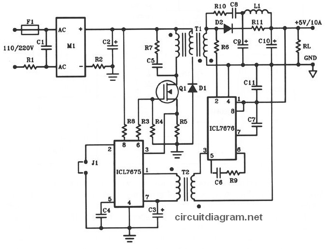
The following diagram illustrates the design of a 50W offline switching power supply circuit. This circuit is powered by a MOSFET, specifically the BUZ80A/IXTP4N8 for 220V AC input and the GE IRF823 for 110V AC input voltage. The output...
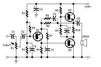
The total electric current drawn by the circuit should be measured by connecting the probes of a multimeter across the positive output of the power supply and the positive rail input of the amplifier. The expected current value is...
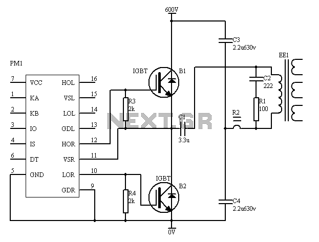
The PM4040F is utilized in switching power supply applications for medium power ranges. It is designed to drive power supplies between 200W and 800W, as illustrated in the accompanying bridge circuit. For power applications below 1000W, an alternative circuit...
This application note outlines the development and implementation of a Digital Weigh-Scale (DWS) utilizing Zilog's Z8 Encore! Microcontroller. The reference design provides a ready-to-use DWS solution that is easily scalable for measuring high-capacity loads. An external high-resolution Analog-to-Digital Converter...
Tubular xenon lamp power, high brightness, known as the "little sun." Tubular xenon lamp wiring is illustrated in Figure 2-6. The tubular xenon lamp is a high-intensity discharge (HID) light source, characterized by its ability to produce a bright white...
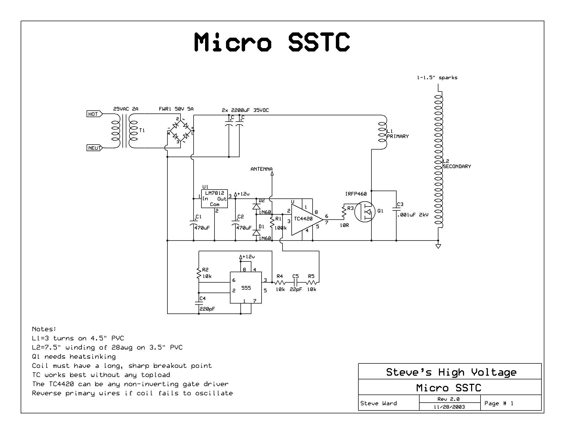
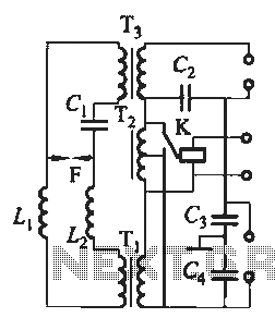
A solid-state flyback driver based on a micro solid-state Tesla coil circuit created by Steve Ward. The schematic is reprinted here with credits to Steve Ward. Instead of an air-core Tesla Coil setup, a flyback transformer is utilized. An...