
3w 5w audio amplifier circuit schematic

To accurately measure the total electric current in the circuit, it is essential to ensure that the multimeter is properly configured for current measurement. This involves connecting the multimeter in series with the circuit component whose current is to be measured. In this case, the measurement should occur between the power supply's positive output and the amplifier's positive rail input.
The multimeter should be set to the appropriate current range, ideally exceeding the expected 700 mA to prevent damage to the device. Once the probes are connected, the circuit can be powered on, and the multimeter will display the current flowing through the circuit.
If the measured current deviates from the target value of 700 mA, adjustments can be made by modifying the resistance of R8. This resistor is likely part of a feedback network or current-limiting circuit, and altering its value will affect the overall current flow. Increasing R8 will reduce the current, while decreasing R8 will increase it. It is important to make small adjustments and re-measure the current to avoid overshooting the desired value.
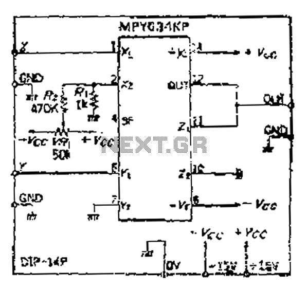
In summary, the procedure for measuring and adjusting the total electric current in the circuit is straightforward, involving proper multimeter setup, careful measurement, and precise adjustments to R8 as needed to maintain the target current level of 700 mA.Total electric current drawing of the circuit, recommended measured by inserting the probes of an multimeter across the positive output with the power supply and also the positive rail input with the amplifier, should be 700mA. Adjust R8 to obtain this value if needed. 🔗 External reference
Related Circuits

This LED VU Meter (volume unit) is designed to monitor and display power levels present at the speaker terminals of a stereo audio power amplifier. The levels are represented in ten discrete steps using ten LEDs for each channel,...
This circuit amplifies voice audio in the frequency range of 50 to 10,000 Hz with minimal distortion and is capable of driving a low impedance load of up to 16 ohms. It operates on a DC voltage of 6...

This circuit is a compact timer designed to keep the headlights of a car illuminated for approximately 1.5 minutes before automatically turning them off. By integrating this circuit into a vehicle, users can access dark areas without the need...
The circuit is straightforward yet capable of outstanding performance. It has been specifically designed as an amplifier for the digital sound card in a computer. Audio input can be sourced from any two-channel line-level device such as a television,...
Although the inputs are differential, the right amplifier has a bias current greater than 800 nA. Therefore, the input coupling capacitor should be considered. It is important to note that the resistance value on the input side should also...
An LED flasher circuit can be constructed using a 555 integrated circuit (IC). The use of the 555 IC allows for greater flexibility in adjusting the flashing rate of the LED. This LED flasher circuit is similar to other...